


Active Crossover Circuit-Schematic-Design and Diagram
#active crossover
#LM833
#HiFi
#audio filter
#2-way crossover
#circuit design
#schematic
#DIY audio
#sound engineering
#frequency divider
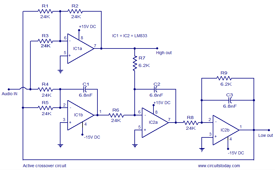
Description: Active crossover circuit design, circuit diagram, schematic, DIY active crossover circuit, HiFi audio crossover, 2-way crossover circuit using LM833.
The active crossover circuit is an essential component in high-fidelity audio systems, allowing for the separation of audio signals into different frequency bands before amplification. This particular design focuses on a 2-way crossover configuration utilizing the LM833 operational amplifier, known for its low noise and high performance characteristics, which enhance audio quality.
In this circuit, the input audio signal is split into two frequency ranges: the low-frequency signals are directed to a subwoofer or woofer, while the high-frequency signals are sent to a tweeter. The crossover point, typically adjustable, determines the frequency at which the audio signal is divided.
The schematic includes two main sections: the low-pass filter and the high-pass filter. The low-pass filter allows frequencies below the crossover point to pass through while attenuating higher frequencies. Conversely, the high-pass filter permits frequencies above the crossover point to pass while blocking lower frequencies.
Components in the circuit include resistors and capacitors that define the filter characteristics, as well as the LM833 op-amps that provide the necessary gain and buffering for the signals. The design can be implemented on a PCB or a breadboard for prototyping, allowing for adjustments and fine-tuning of the crossover frequency and filter slope.
For optimal performance, careful attention should be paid to component selection, layout, and grounding to minimize noise and interference. This active crossover circuit is ideal for DIY enthusiasts looking to enhance their audio systems with precise control over frequency distribution, resulting in improved sound clarity and overall listening experience.Active crossover circuit design,circuit diagram,schematic, diy active crossover circuit,HiFi audio crossover, 2 (band) way crossover circuit using LM833..
The active crossover circuit is an essential component in high-fidelity audio systems, allowing for the separation of audio signals into different frequency bands before amplification. This particular design focuses on a 2-way crossover configuration utilizing the LM833 operational amplifier, known for its low noise and high performance characteristics, which enhance audio quality.
In this circuit, the input audio signal is split into two frequency ranges: the low-frequency signals are directed to a subwoofer or woofer, while the high-frequency signals are sent to a tweeter. The crossover point, typically adjustable, determines the frequency at which the audio signal is divided.
The schematic includes two main sections: the low-pass filter and the high-pass filter. The low-pass filter allows frequencies below the crossover point to pass through while attenuating higher frequencies. Conversely, the high-pass filter permits frequencies above the crossover point to pass while blocking lower frequencies.
Components in the circuit include resistors and capacitors that define the filter characteristics, as well as the LM833 op-amps that provide the necessary gain and buffering for the signals. The design can be implemented on a PCB or a breadboard for prototyping, allowing for adjustments and fine-tuning of the crossover frequency and filter slope.
For optimal performance, careful attention should be paid to component selection, layout, and grounding to minimize noise and interference. This active crossover circuit is ideal for DIY enthusiasts looking to enhance their audio systems with precise control over frequency distribution, resulting in improved sound clarity and overall listening experience.Active crossover circuit design,circuit diagram,schematic, diy active crossover circuit,HiFi audio crossover, 2 (band) way crossover circuit using LM833..

Nescaf mod
The NESCAF audio filter is a compact and cost-effective circuit that enhances amateur radio setups. It is particularly beneficial for radio receivers or transceivers that do not include an optional CW filter. However, one limitation of this filter is the...
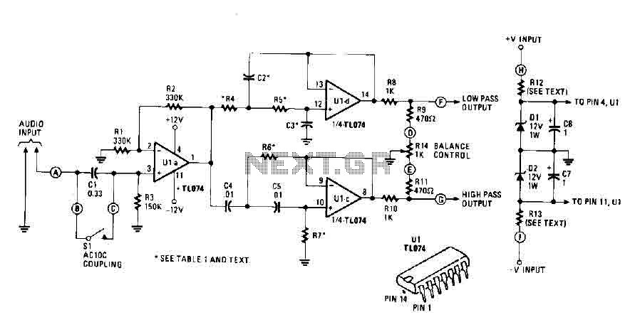
Active crossover circuit with TL074
An audio source, such as a mixer, preamp, EQ, or recorder, is connected to the input of the Electronic Crossover Circuit. The signal can be either AC or coupled, depending on the setting of switch 51, which controls the non-inverting...
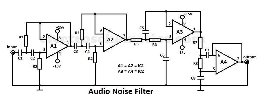
Audio Noise Filter Circuit
This audio noise filter circuit is a bandpass filter designed for the audio frequency range. It effectively filters out unwanted signals that fall below or above the audio frequency spectrum.
The audio noise filter circuit operates as a bandpass filter, which...
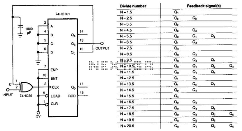
Divide-By-N + 1/2 Circuit
This circuit divides the input signal by +1/2 instead of dividing by an integer. With the feedback connections as illustrated in the figure, the circuit effectively divides by 3.5. Point C ultimately determines when the input triggers the 74HC161 4-bit...
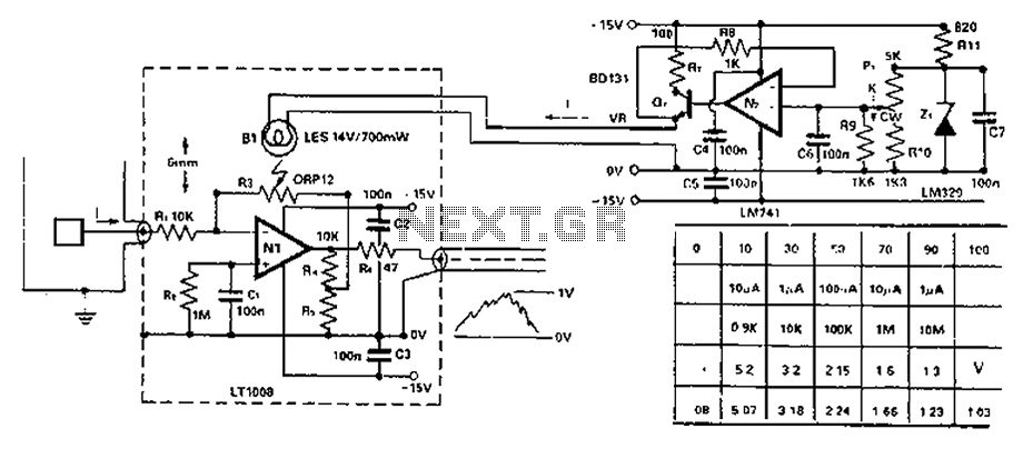
The HiFi amplifier 300B
The 300B is a highly reliable power amplifier transistor with excellent characteristics. The circuit should be designed to fully utilize the outstanding features of the 300B. To address the warm-up time, the filament of the 300B is paired with the...
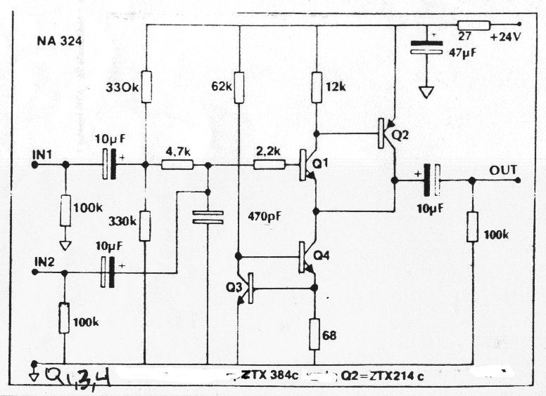
Better-Sounding Active Crossovers
Can anyone explain the function of the four transistors located on the right-hand side of each of McBride's schematics?
The presence of four transistors on the right-hand side of McBride's schematics typically indicates a specific function related to signal amplification, switching,...
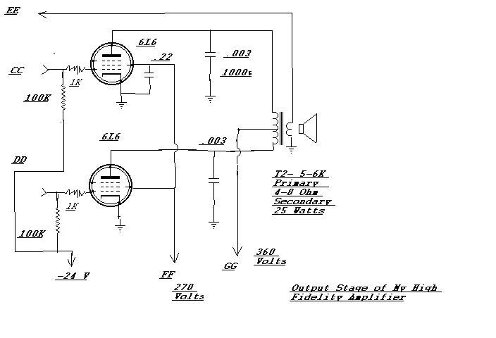
Homemade HiFi
An amplifier designed to complement an antique Meissner AM High Fidelity tuner that has been restored. Upon completion, the amplifier delivered such impressive sound quality that it became the preferred choice for listening to CDs while working. The only new...
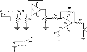
How to Read a Schematic
Electronic circuits are presented in schematic form. A schematic is essentially a map that illustrates the path of current through various components. Each component is represented by a symbol, typically accompanied by a label or a value, or both. The...
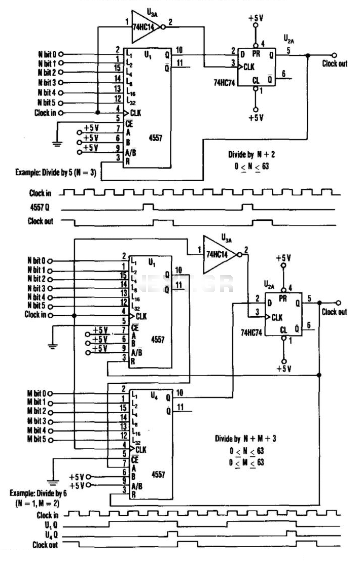
Programmable Frequency Divider
This divider utilizes a variable-length shift register, a type-D flip-flop, and an inverter. The clock signal is connected to the clock input of the flip-flop, while the output of the shift register is connected to the D input of the...