


Audio Controlled Mains Switch Circuit
#audio switch
#mains switch
#signal detection
#manual operation
#reset switch
#time delay
#audio equipment
#video equipment
#power control
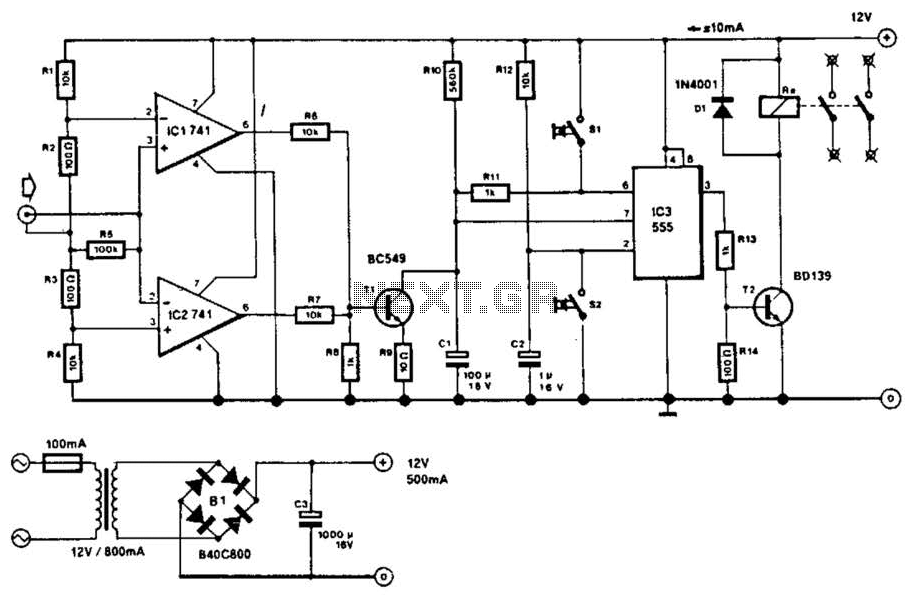
Description: This circuit will disconnect the line supply to audio or video equipment if there has been no input signal for approximately 2 seconds. Switch SI provides manual operation, while switch S2 functions as a reset mechanism. This circuit allows time for changing a tape or compact disc. Additionally, around 50 mV of audio signal is required for operation.
The described circuit serves as an automatic power management solution for audio and video equipment, enhancing energy efficiency and user convenience. The primary function is to monitor the presence of an audio or video signal, and if the signal falls below a threshold (approximately 50 mV), the circuit will interrupt the power supply after a delay of about 2 seconds. This feature is particularly useful in scenarios where equipment is idle, preventing unnecessary power consumption.
The circuit includes two key switches: SI and S2. Switch SI is designed for manual operation, allowing users to override the automatic shut-off feature when needed. For instance, if a user is aware that they will be changing a tape or compact disc, they can manually keep the circuit engaged. Switch S2 serves as a reset mechanism, enabling the user to restore power to the equipment after it has been turned off due to inactivity.
The design likely incorporates a timing circuit, such as a capacitor-resistor (RC) network, to establish the 2-second delay. When the audio signal is present, the voltage across the capacitor remains above the threshold, keeping the circuit active. Once the signal drops below the required 50 mV, the capacitor begins to discharge, and if it drops below a certain level within the 2-second window, a relay or transistor may be triggered to cut off the power supply.
This circuit can be implemented using standard electronic components such as resistors, capacitors, transistors, and relays. The selection of components should ensure that the circuit operates reliably within the specified voltage and current ratings of the audio or video equipment it is designed to protect. Overall, this circuit design exemplifies a practical approach to reducing energy waste in consumer electronics while providing essential user controls for manual operation and reset functionality. This circuit will switch off the line supply to audio or video equipment if there has been no input signal for about 2 seconds. SI provides manual operation and S2 acts as a reset. This circuit allows for time to change a tape or compact disc. About 50 mV of audio signal is necessary.
The described circuit serves as an automatic power management solution for audio and video equipment, enhancing energy efficiency and user convenience. The primary function is to monitor the presence of an audio or video signal, and if the signal falls below a threshold (approximately 50 mV), the circuit will interrupt the power supply after a delay of about 2 seconds. This feature is particularly useful in scenarios where equipment is idle, preventing unnecessary power consumption.
The circuit includes two key switches: SI and S2. Switch SI is designed for manual operation, allowing users to override the automatic shut-off feature when needed. For instance, if a user is aware that they will be changing a tape or compact disc, they can manually keep the circuit engaged. Switch S2 serves as a reset mechanism, enabling the user to restore power to the equipment after it has been turned off due to inactivity.
The design likely incorporates a timing circuit, such as a capacitor-resistor (RC) network, to establish the 2-second delay. When the audio signal is present, the voltage across the capacitor remains above the threshold, keeping the circuit active. Once the signal drops below the required 50 mV, the capacitor begins to discharge, and if it drops below a certain level within the 2-second window, a relay or transistor may be triggered to cut off the power supply.
This circuit can be implemented using standard electronic components such as resistors, capacitors, transistors, and relays. The selection of components should ensure that the circuit operates reliably within the specified voltage and current ratings of the audio or video equipment it is designed to protect. Overall, this circuit design exemplifies a practical approach to reducing energy waste in consumer electronics while providing essential user controls for manual operation and reset functionality. This circuit will switch off the line supply to audio or video equipment if there has been no input signal for about 2 seconds. SI provides manual operation and S2 acts as a reset. This circuit allows for time to change a tape or compact disc. About 50 mV of audio signal is necessary.
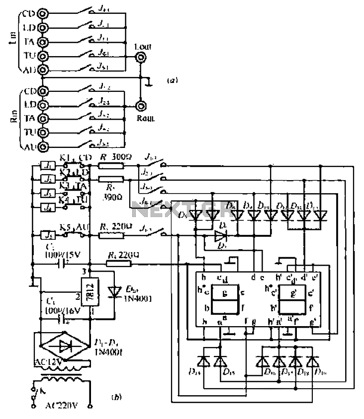
A five-way dual-channel audio switching circuit
Can simulate the character Mu symbol. A bone dish SET code is needed that effectively manages the decimal point. An inverted J is required to open its mouth. Left foot circuit diagram.
The project involves designing a circuit that simulates the...
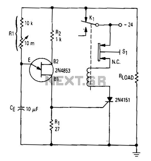
Simple-time-delay
After the first cycle, the relay will normally be energized. When the normally closed pushbutton 51 is activated, the SCR turns off, the relay is de-energized, and power is applied to the relaxation oscillator and the load. After a time...
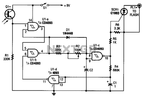
Time Delay Flash Trigger Circuit Circuit
The circuit is built around a single 4093 quad 2-input NAND Schmitt trigger. Two gates from that quad package (U1-a and U1-b) are configured as a set-reset flip-flop.
The 4093 integrated circuit (IC) contains four independent 2-input NAND gates with Schmitt...
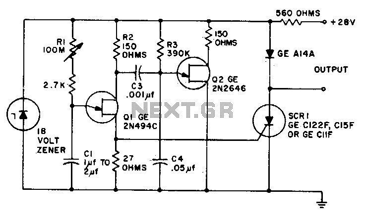
Ultra-precise long time delay relay
Predictable time delays ranging from 0 milliseconds to over 3 minutes can be achieved without the use of a large electrolytic timing capacitor. Instead, a stable low leakage paper or mylar capacitor is employed, effectively reducing the peak point current...
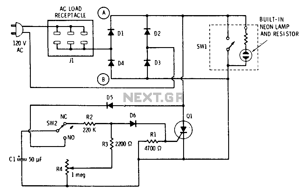
Tarry light
The push button and potentiometer initiate a time delay that turns a light on and then automatically turns it off again after a predetermined time. The potentiometer can be set for a delay of a few seconds to just under...
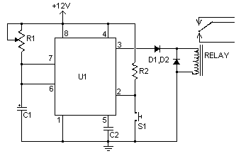
Time Delay Relay
A time delay relay is a relay that stays on for a certain amount of time once activated. This time delay relay is made up of a simple adjustable timer circuit which controls the actual relay. The time is adjustable...
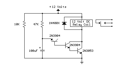
Power-On Time Delay Relay
Here's a power-on time delay relay circuit that takes advantage of the emitter/base breakdown voltage of an ordinary bi-polar transistor. The reverse connected emitter/base junction of a 2N3904 transistor is used as an 8 volt zener diode which creates a...
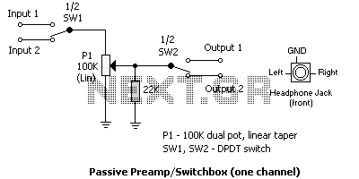
Desktop Audio Switch box
One of the more frequently requested projects on HeadWize has been a switchbox for selecting multiple audio inputs. I built this passive preamp/switchbox several years ago to switch between two stereo sources (a portable FM tuner and portable CD player)...
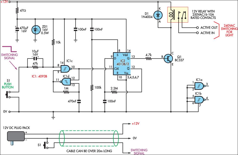
Low-Voltage Remote Mains Switch
This circuit enables the remote control of a 240V mains appliance, such as a light bulb, through low-voltage cabling and a pushbutton switch. The mains appliance is activated using a suitably-rated relay. All electronic components are housed in an ABS...