


Audio Voice-Over Circuit using LM380
#LM380
#microphone preamp
#voice-over
#audio signal
#push-to-talk
#amplifier
#audio priority
#sound circuit
#voice circuit
#audio switch
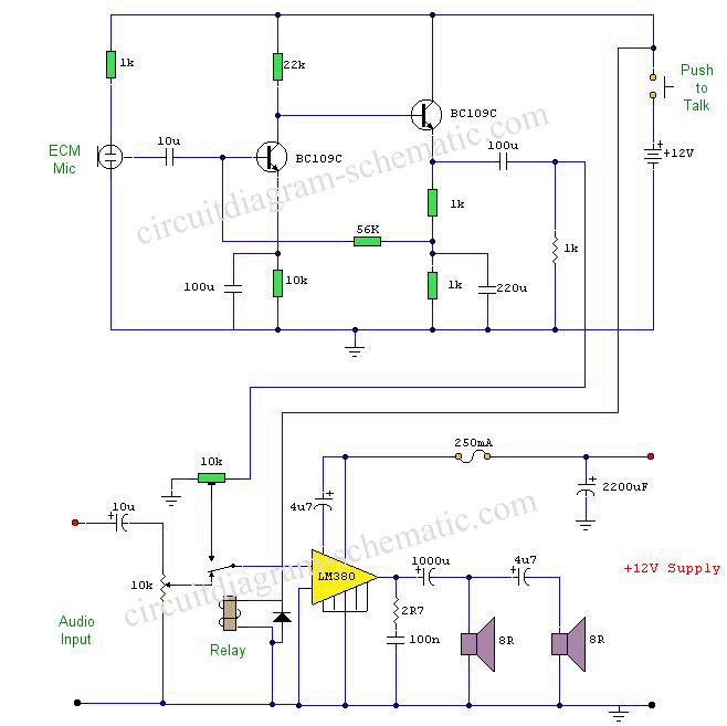
Description: This circuit diagram represents a microphone preamplifier, specifically designed to prioritize voice signals over other audio inputs. In its basic configuration, the circuit includes a microphone unit and a change-over switch that connects to an amplifier. When the push-to-talk switch is activated, the output from the microphone takes precedence over the audio signal from the amplifier.
The microphone preamp circuit is essential in applications where clear voice communication is critical, such as in intercom systems, public address systems, and two-way radios. The circuit typically consists of a microphone, an operational amplifier (op-amp), resistors, capacitors, and a push-to-talk (PTT) switch.
In operation, the microphone captures sound waves and converts them into an electrical signal. This weak signal is then fed into the op-amp, which amplifies it to a usable level. The change-over switch allows the user to select between the microphone input and other audio sources. When the PTT switch is pressed, it activates the microphone circuit, ensuring that the voice signal is prioritized and clearly transmitted over any background audio.
The design may include additional components such as low-pass filters to eliminate high-frequency noise and ensure a clean audio output. Furthermore, careful consideration must be given to the power supply requirements of the op-amp to maintain optimal performance. Overall, this microphone preamp circuit is a vital component in achieving effective voice communication in various electronic systems.This circuit is a circuit diagram of a microphone preamp and circuits (voice circuit) has priority over any other audio signal. In its simplest form, the voice-over only the microphone unit and the change-over switch eating an amplifier, the output of the microphone has priority over the amplifiers audio signal when the push-to-talk switch is pressed
The microphone preamp circuit is essential in applications where clear voice communication is critical, such as in intercom systems, public address systems, and two-way radios. The circuit typically consists of a microphone, an operational amplifier (op-amp), resistors, capacitors, and a push-to-talk (PTT) switch.
In operation, the microphone captures sound waves and converts them into an electrical signal. This weak signal is then fed into the op-amp, which amplifies it to a usable level. The change-over switch allows the user to select between the microphone input and other audio sources. When the PTT switch is pressed, it activates the microphone circuit, ensuring that the voice signal is prioritized and clearly transmitted over any background audio.
The design may include additional components such as low-pass filters to eliminate high-frequency noise and ensure a clean audio output. Furthermore, careful consideration must be given to the power supply requirements of the op-amp to maintain optimal performance. Overall, this microphone preamp circuit is a vital component in achieving effective voice communication in various electronic systems.This circuit is a circuit diagram of a microphone preamp and circuits (voice circuit) has priority over any other audio signal. In its simplest form, the voice-over only the microphone unit and the change-over switch eating an amplifier, the output of the microphone has priority over the amplifiers audio signal when the push-to-talk switch is pressed
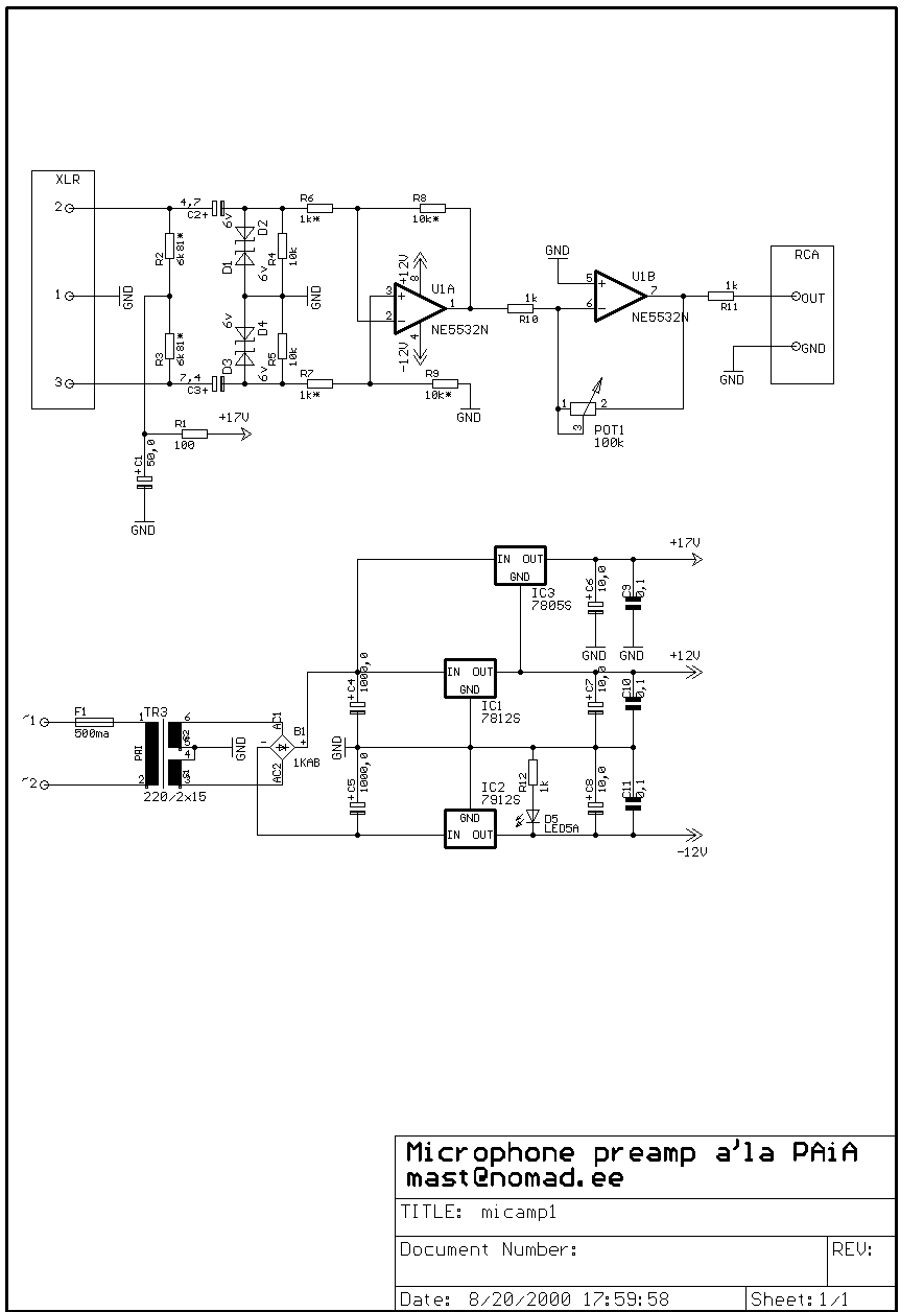
Balanced microphone preamp project
Well, it's pretty much a PAiA preamp - usual input circuitry followed by one half of dual op-amp rigged in fixed 20dB amplification circuitry, followed by second stage which is adjustable for up to 40dB amplification, for up to 60dB...
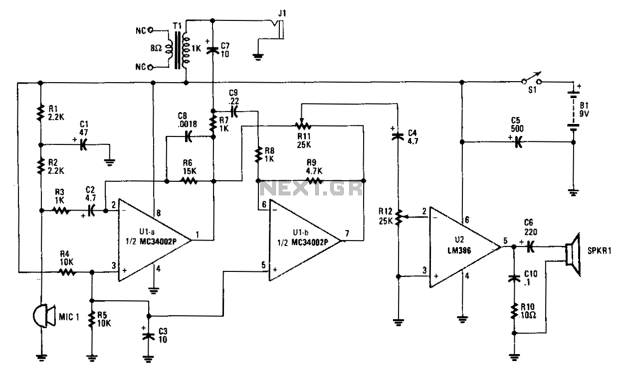
Hands-off-intercom
Amplifier A increases the microphone's output to a usable level. The output signal is fed to op amp B, which inverts the signal by 180 degrees. A balance-control potentiometer connects across the outputs of amplifiers A and B. If an...
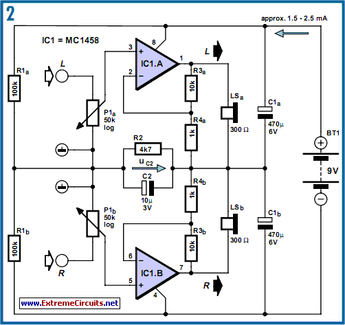
DC-Coupled Audio Amplifier circuit
Designs for audio amplifiers with DC coupling to the load are not frequently seen today, despite offering distinct advantages.
Audio amplifiers that employ DC coupling to the load provide several benefits that can enhance performance in specific applications. In traditional audio...
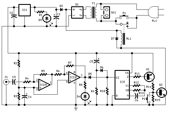
Amplifier Timer
Turns off your amplifier when idle for 15 minutes. Fed by amplifier tape-output. This circuit turns off an amplifier or any other device when a low-level audio signal fed to its input is absent for 15 minutes at least. Pushing...
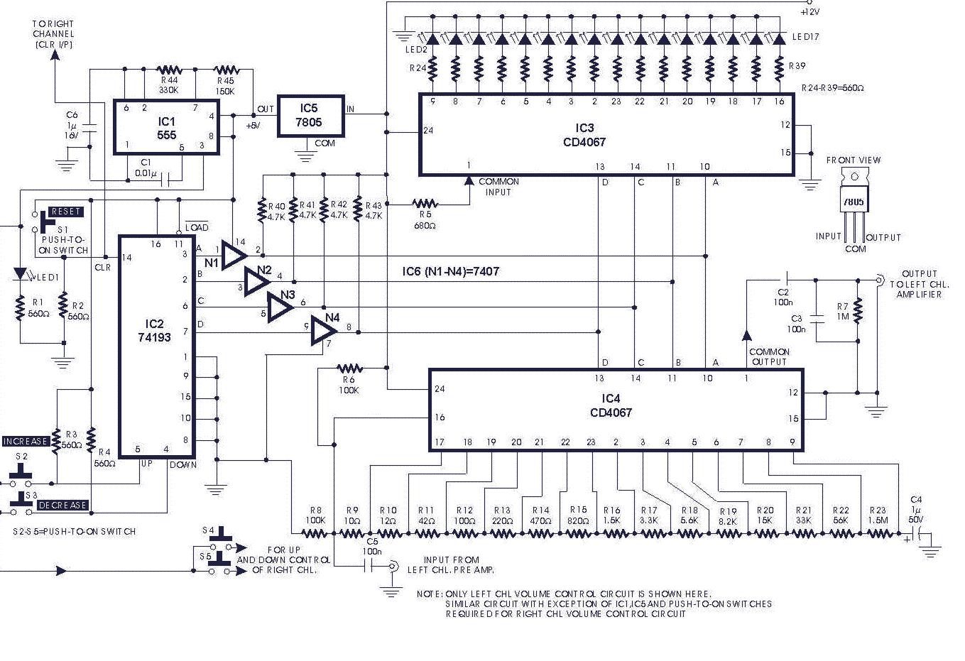
audio circuits 20
The gain of the single-stage virtual earth amplifier IC1 is determined by the drain-source resistance of the field-effect transistor (FET). Resistors R1, R2, and R3 linearize the FET's voltage-current characteristic. A control voltage is derived from the output signal using...
electronic circuit amplifier
The LM380 is a power audio amplifier designed for consumer applications. To minimize system costs, the gain is internally fixed at 34 dB. It features a unique input stage that allows for ground-referenced input signals. The output automatically self-centers to...
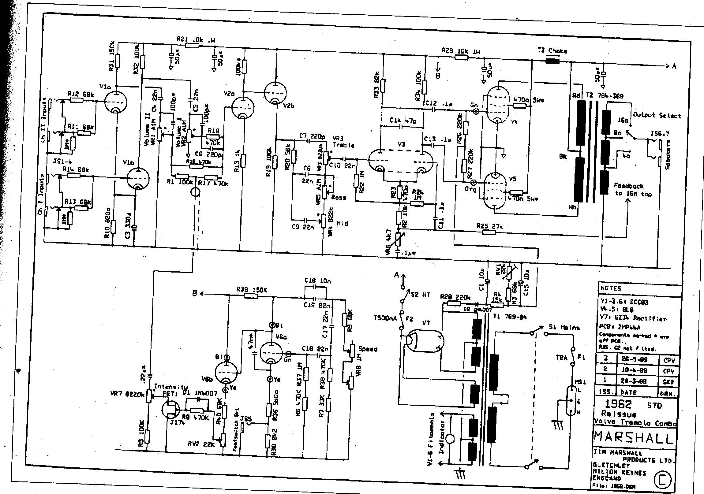
Marshall JTM-45 and 62 Bluesbreaker Reissue Modifications
The Sovtek 5881 tubes included in these amplifiers are low-quality and produce a corresponding sound. It is advisable to replace all tubes with a Sovtek GZ34, Valve Art or GT KT66 tubes, and Ei Gold preamp tubes. The KT66 tubes...
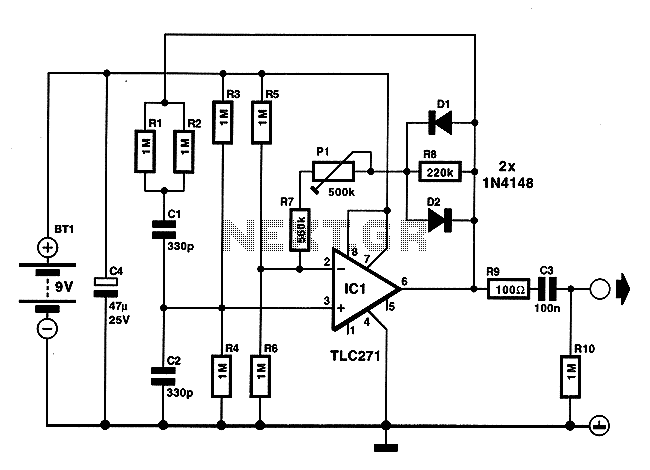
Low energy consumption audio signal generator
On occasions when it is necessary to determine if an amplifier is functioning, the most effective tool is an acoustic signal source with a frequency around 1 kHz. The specifications can be considered flexible, as rapid tests typically do not...
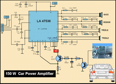
Schematic MP3 Car Audio Power AmplifierCircuits
This is a diagram of a car audio active loudspeaker utilizing the LF353 operational amplifier from National Semiconductor. For optimal performance, the NE5532 is recommended to split the audio signal into three frequency bands using an active filter. The SANYO...