


Ballroom synchronous voice switching circuit with music
#condenser microphone
#sound sensing
#signal conversion
#voice switching
#music
#synchronous
#audio processing
#sound detection
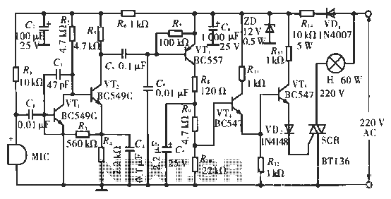
Description: The circuit utilizes condenser microphones to detect sound and convert it into signal variations. This signal is then processed through directly coupled transistors VT1 and VT2, which form an amplification stage before being fed into a switching circuit. The switching circuit is composed of transistors VT3, VT4, and VT5, activating only when the sound signal is present.
The described circuit operates as a sound-activated switch, leveraging the properties of condenser microphones to detect acoustic signals. The condenser microphones are sensitive to sound waves, converting them into electrical signals that vary in amplitude according to the sound intensity. These signals are then routed to a pair of directly coupled transistors, VT1 and VT2, which serve as an amplifier stage. This amplification is crucial for enhancing the weak signals from the microphones to a level suitable for further processing.
Transistors VT1 and VT2 are configured in a common-emitter arrangement, which provides significant voltage gain. The output from this stage is then sent to the switching circuit, which consists of transistors VT3, VT4, and VT5. These transistors are arranged to operate as a relay system, where the presence of a sufficient amplified signal from the microphones triggers the switching action.
The switching circuit is designed to activate only when the input signal exceeds a predetermined threshold, ensuring that background noise does not inadvertently trigger the circuit. This is achieved through careful biasing of the transistors, allowing for precise control over the switching behavior. When the sound signal is detected and amplified, it causes VT3 to conduct, which in turn activates VT4 and VT5, completing the circuit and enabling the connected load.
This configuration allows for a wide range of applications, including automatic lighting systems, sound-activated alarms, and other devices where sound detection is required. The design emphasizes reliability and responsiveness, ensuring that the circuit only activates in response to meaningful sound events, thus minimizing false triggers from ambient noise. Overall, the circuit exemplifies a practical application of sound sensing technology in electronic systems.Circuit works: a circuit with condenser microphones to sense sound and converts it into a signal changes, and then put through directly coupled transistors VT1 and VT2 composed of amplifier amplified to the switching circuit. Switch circuit by the VT3, VT4 and VT5 constitution, only the circuit senses the sound when the signal is turned on.
The described circuit operates as a sound-activated switch, leveraging the properties of condenser microphones to detect acoustic signals. The condenser microphones are sensitive to sound waves, converting them into electrical signals that vary in amplitude according to the sound intensity. These signals are then routed to a pair of directly coupled transistors, VT1 and VT2, which serve as an amplifier stage. This amplification is crucial for enhancing the weak signals from the microphones to a level suitable for further processing.
Transistors VT1 and VT2 are configured in a common-emitter arrangement, which provides significant voltage gain. The output from this stage is then sent to the switching circuit, which consists of transistors VT3, VT4, and VT5. These transistors are arranged to operate as a relay system, where the presence of a sufficient amplified signal from the microphones triggers the switching action.
The switching circuit is designed to activate only when the input signal exceeds a predetermined threshold, ensuring that background noise does not inadvertently trigger the circuit. This is achieved through careful biasing of the transistors, allowing for precise control over the switching behavior. When the sound signal is detected and amplified, it causes VT3 to conduct, which in turn activates VT4 and VT5, completing the circuit and enabling the connected load.
This configuration allows for a wide range of applications, including automatic lighting systems, sound-activated alarms, and other devices where sound detection is required. The design emphasizes reliability and responsiveness, ensuring that the circuit only activates in response to meaningful sound events, thus minimizing false triggers from ambient noise. Overall, the circuit exemplifies a practical application of sound sensing technology in electronic systems.Circuit works: a circuit with condenser microphones to sense sound and converts it into a signal changes, and then put through directly coupled transistors VT1 and VT2 composed of amplifier amplified to the switching circuit. Switch circuit by the VT3, VT4 and VT5 constitution, only the circuit senses the sound when the signal is turned on.

Music synthesizer
The music synthesizer mode offers three operational modes: playing a note, playing one of four pre-stored tunes, or recording a tune for later playback.
In the music synthesizer mode, the circuit is designed to facilitate three distinct functionalities, enhancing user interaction...
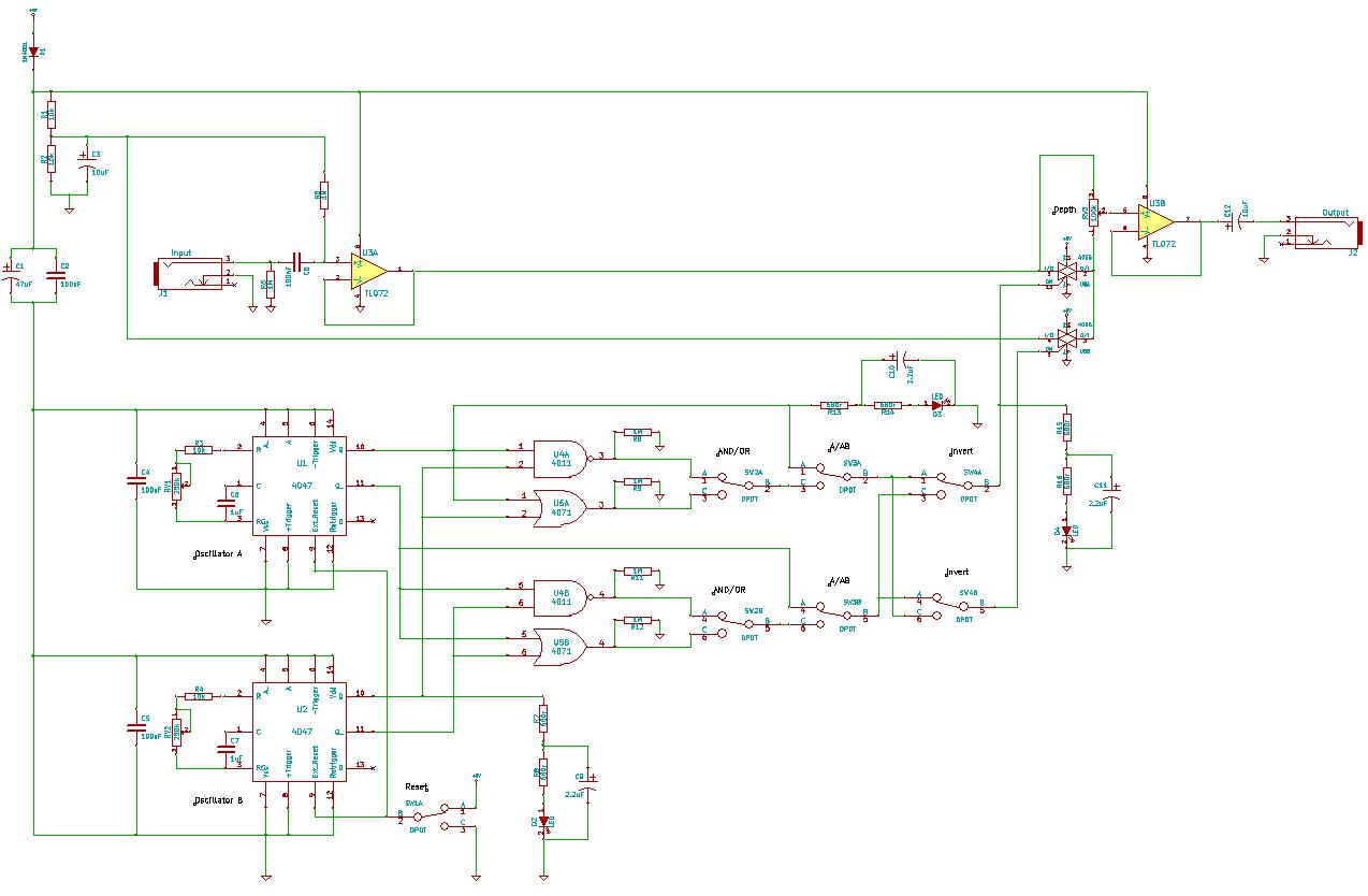
4047/4066 audio slicer
You need to connect pins 1 and 13 of the 4053 to the virtual ground rail (top of C4), not the circuit's 0V rail.
The CD4053 is a triple 2-channel analog multiplexer/demultiplexer integrated circuit, widely used for routing analog signals...
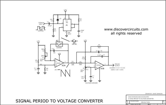
PULSE PERIOD TO VOLTAGE CONVERTER
This circuit is designed to convert a square wave input signal into a voltage output. The voltage produced is proportional to the time interval between the edges (period) of the signal, rather than its frequency. The operational range of the...
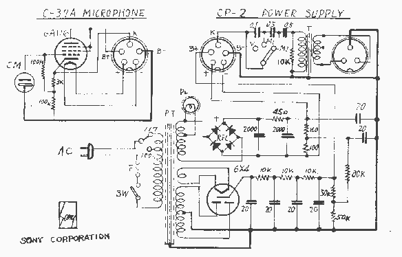
Sony C-37A Condenser Microphone
One of my prize pieces of equipment is a pair of Sony C-37A large capsule tube, condenser microphones. I bought these from the radio station at college because they were getting hard to use, and an intermittent connector problem resulted...
/cardioid condenser microphones
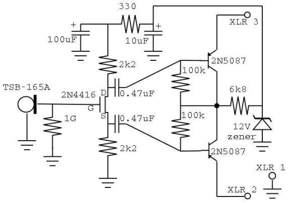
These small diaphragm condenser microphones were constructed as a project for an Electronics III class. The circuit layout and design of the microphones are inspired by DIY microphone projects by Scott Helmke (the "Alice" mic) and Stefan Avalos' small cardioids....
Phantom and T powering for condenser microphones
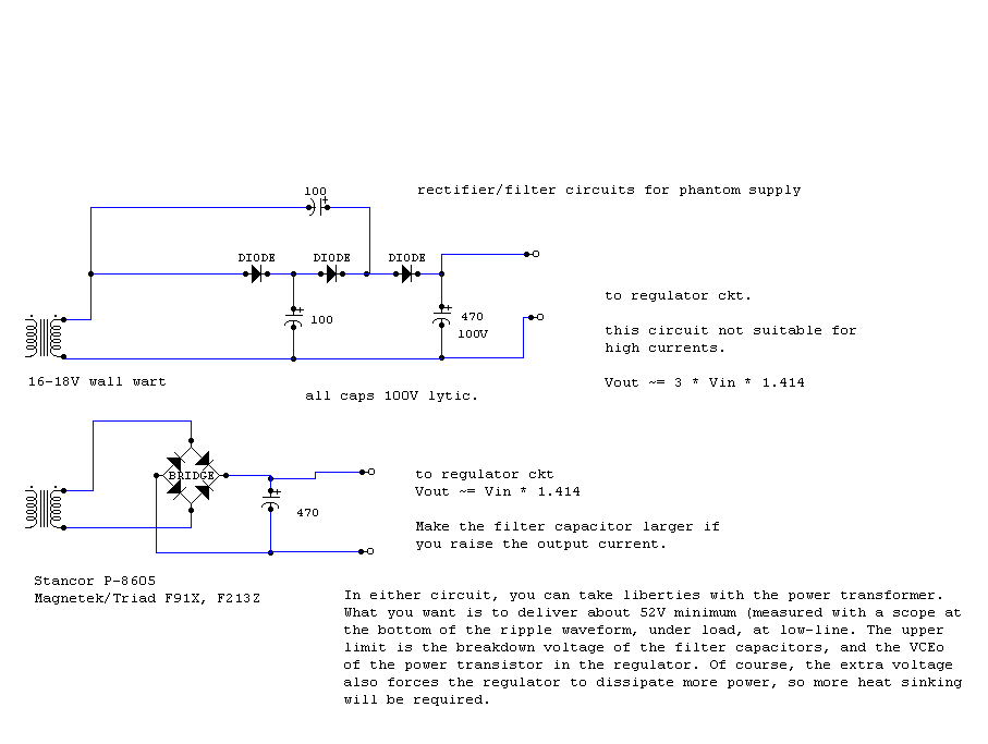
An RF condenser design powered by 12V was supplied to the microphone through the microphone cable using a phantom circuit. This marks the first known application of a phantom circuit for microphone powering. Around 1970, Neumann introduced the Fet-80 series...
ARRL Handbook Audio Intelligibility Enhancer
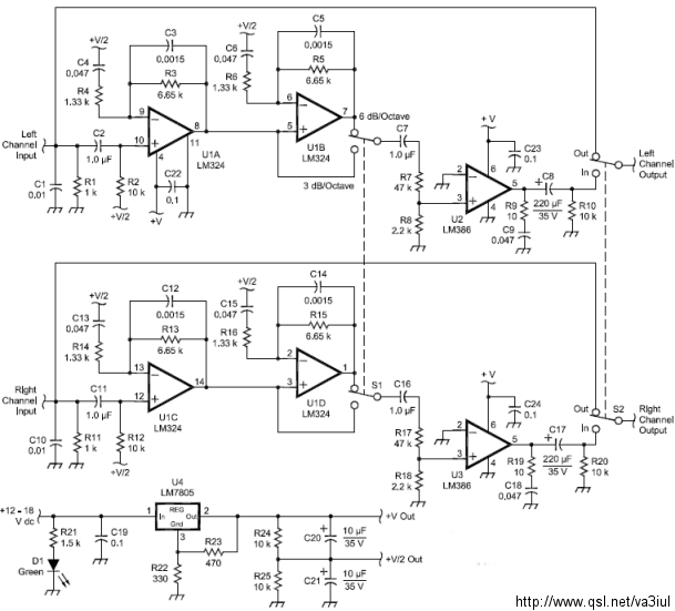
Assistance is sought for building the N4GG audio intelligibility enhancer project as detailed in the ARRL Handbook. A circuit board has been ordered from Far Circuits, but there are difficulties in sourcing the necessary components. Attempts have been made to...
3 V/5 V Low Power Synchronous Voltage-to-Frequency Converter
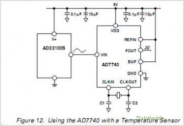
The ADF4107 Frequency Synthesizer can be used to implement local oscillators in the upconversion and downconversion sections of wireless receivers and transmitters. It consists of a low noise digital phase frequency detector (PFD), a precision charge pump, a programmable reference...
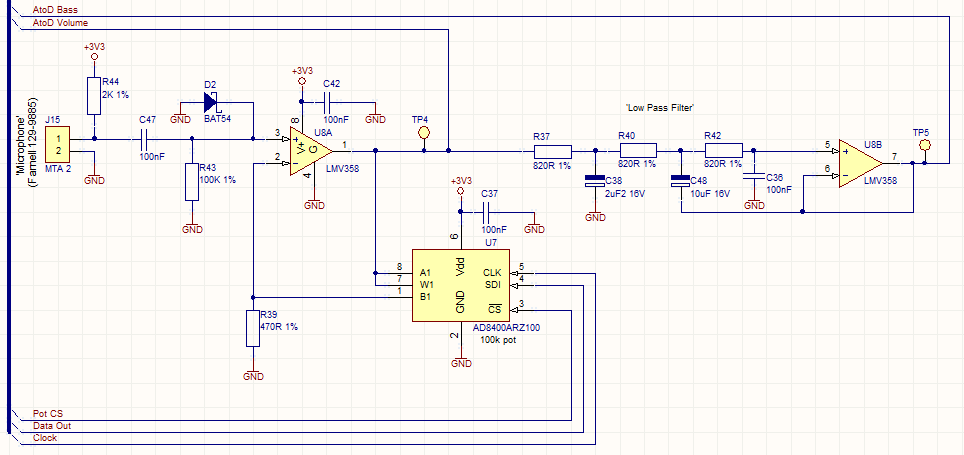
Audio Beat Detect ?« Electronic Product Design
This circuit employs a digital potentiometer to enable the microcontroller to automatically adjust the circuit's gain according to the ambient audio volume. However, a standard potentiometer can be used if automatic adjustment is unnecessary. The low-pass filter design is based...