


Bass circuit diagram

Description: The circuit operates by processing an input signal through IC1-1 and a fourth-order low-pass filter, which provides a slope of 24 dB/octave with a cutoff frequency (fc) of 70 Hz and an amplification of 8.2 dB. The output from this filter is then sent to IC2-1, an inverting buffer amplifier that amplifies the low-frequency signal by a factor of 10. This significantly enhances the strength of the low-frequency signal compared to the original signal. The signals are then mixed at IC2-3 with the aid of capacitors C4 and C3, and the mixed output is taken from capacitor C5. The mixing process allows for control over the amount of low-frequency signal relative to the original signal, ensuring that when the control signal (W) is turned off, the output from C5 remains authentic, with the gain level set to 0 dB. Component selection is critical, with a requirement that the low-pass cutoff frequency resistors (R, C) have an error of less than 1%. Resistors R2 to R5 can utilize 5% tolerance resistors from the 1/8W RJ series. Non-polar capacitors from the CL series are used, while C4, C3, and C5 are tantalum electrolytic capacitors. It is recommended to use a digital measuring device for selecting RC components, and the circuit incorporates the TL084 IC. This circuit should be connected in series between the signal source and the amplifier.
The circuit design utilizes a fourth-order low-pass filter implemented through IC1-1, which effectively attenuates high-frequency signals while allowing low-frequency signals to pass through. The specified cutoff frequency of 70 Hz ensures that signals below this frequency are amplified, while those above are significantly reduced, achieving a slope of 24 dB per octave. This is crucial for applications where low-frequency signal integrity is essential, such as audio processing or sensor signal conditioning.
The inverting buffer amplifier IC2-1 is configured to provide a gain of 10, which boosts the low-frequency signal's amplitude, making it suitable for further processing. The selection of components such as resistors and capacitors is guided by their tolerances to maintain circuit performance. Resistors R2 to R5, chosen from the 5% tolerance category, play a vital role in setting the filter characteristics and gain levels. The use of tantalum electrolytic capacitors for C4, C3, and C5 ensures stability and reliability in the circuit's performance, particularly in handling low-frequency signals.
The mixing stage, facilitated through IC2-3, combines the buffered low-frequency signal with the original signal, allowing for dynamic control of the output. The output from C5 is critical, as it provides the mixed signal while maintaining fidelity to the original input when the control signal (W) is deactivated. This design feature ensures that the circuit can adapt to varying signal conditions without introducing unwanted artifacts.
Overall, the described circuit is engineered for precision and reliability in low-frequency signal processing, making it suitable for various applications in audio and instrumentation where signal integrity is paramount. Circuit principle: the input signal via IC1-1, and external components of the fourth-order low-pass filter to vary the slope of 24db/oct low-pass processing (figure value fc 70 Hz, A 8.2dB) and then to the IC2 -1 center AC inverting buffer amplifier 10 times amplified output is greatly enhanced low-frequency signal with the original signal strength respectively, by C4, C3 into IC2-3 mixing process, mixed-signal output from the C5. Mixed control the amount of W low-frequency signal with the original signal, in order to ensure that when W Off Ends C5 of the output signal is authentic, this gain level set to 0 dB.
Component selection: determine the low-pass cutoff frequency R, C error is less than 1%, R2 - R5 can pick from the error of 5% resistors are used 1/8W RJ series; non-polar capacitors CL series, C4, C4, C5 tantalum electrolytic; RC components selected from the best use of digital measuring table, IC with authentic TL084. When using this circuit will be between the signal source and the amplifier connected in series.
The circuit design utilizes a fourth-order low-pass filter implemented through IC1-1, which effectively attenuates high-frequency signals while allowing low-frequency signals to pass through. The specified cutoff frequency of 70 Hz ensures that signals below this frequency are amplified, while those above are significantly reduced, achieving a slope of 24 dB per octave. This is crucial for applications where low-frequency signal integrity is essential, such as audio processing or sensor signal conditioning.
The inverting buffer amplifier IC2-1 is configured to provide a gain of 10, which boosts the low-frequency signal's amplitude, making it suitable for further processing. The selection of components such as resistors and capacitors is guided by their tolerances to maintain circuit performance. Resistors R2 to R5, chosen from the 5% tolerance category, play a vital role in setting the filter characteristics and gain levels. The use of tantalum electrolytic capacitors for C4, C3, and C5 ensures stability and reliability in the circuit's performance, particularly in handling low-frequency signals.
The mixing stage, facilitated through IC2-3, combines the buffered low-frequency signal with the original signal, allowing for dynamic control of the output. The output from C5 is critical, as it provides the mixed signal while maintaining fidelity to the original input when the control signal (W) is deactivated. This design feature ensures that the circuit can adapt to varying signal conditions without introducing unwanted artifacts.
Overall, the described circuit is engineered for precision and reliability in low-frequency signal processing, making it suitable for various applications in audio and instrumentation where signal integrity is paramount. Circuit principle: the input signal via IC1-1, and external components of the fourth-order low-pass filter to vary the slope of 24db/oct low-pass processing (figure value fc 70 Hz, A 8.2dB) and then to the IC2 -1 center AC inverting buffer amplifier 10 times amplified output is greatly enhanced low-frequency signal with the original signal strength respectively, by C4, C3 into IC2-3 mixing process, mixed-signal output from the C5. Mixed control the amount of W low-frequency signal with the original signal, in order to ensure that when W Off Ends C5 of the output signal is authentic, this gain level set to 0 dB.
Component selection: determine the low-pass cutoff frequency R, C error is less than 1%, R2 - R5 can pick from the error of 5% resistors are used 1/8W RJ series; non-polar capacitors CL series, C4, C4, C5 tantalum electrolytic; RC components selected from the best use of digital measuring table, IC with authentic TL084. When using this circuit will be between the signal source and the amplifier connected in series.
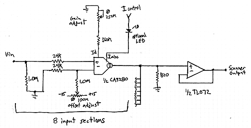
Interpolating Scanner Circuit
This design is for an interpolating scanner, a circuit featuring multiple signal inputs, a control voltage input, and a signal output. The output selectively transitions between inputs, smoothly fading from one to the next as the control voltage increases. A...

Variable Low-Pass Filter Circuit
This second-order low-pass filter utilizes a 741 operational amplifier and can be tuned from 2.5 kHz to 25 kHz. The circuit is beneficial in audio and tone control applications. R1 and R2 are ganged potentiometers.
The described circuit features a second-order...
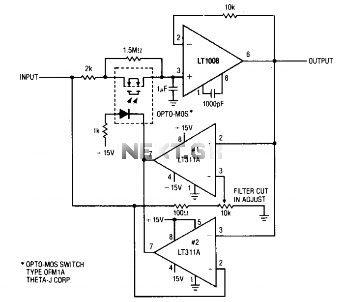
Low-pass filter
This circuit is useful where fast signal acquisition and high precision are required, such as in electronic scales. The filter's time constant is determined by the 2-ohm resistor and the 1 µF capacitor until comparator No. 1 activates. After this...
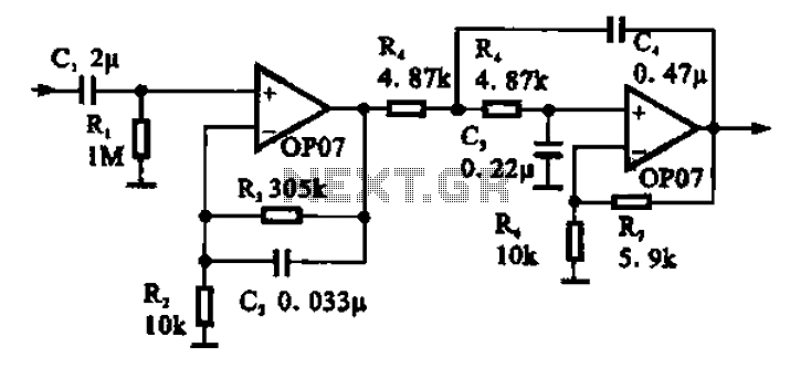
Broadband 0.1 to 10Hz filter amplifier
Broadband 0.1 to 10 Hz filter amplifier. The broadband circuit consists of two operational amplifiers configured as filter amplifiers operating in the frequency range of 0.1 to 10 Hz.
The broadband filter amplifier circuit utilizes two operational amplifiers (op-amps) to achieve...
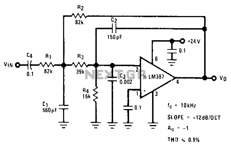
Stylus sand acoustic filter circuit diagrams
The circuit provides a passband gain of 1 with a corner frequency of 10 kHz, designed to eliminate high-frequency noise such as hiss, ticking, and popping sounds.
This circuit operates as a low-pass filter, effectively attenuating frequencies above the specified corner...
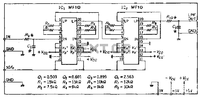
Cutoff frequency 48dB-octSCF low-pass filter circuit
To create a Butterworth low-pass filter with a 12 dB/octave roll-off, four second-order (12 dB/oct) filter blocks are connected in series. This configuration is intended to achieve flat response characteristics across the frequency spectrum. The values for each stage of...
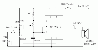
Factory Alarm
The frequency is controlled by pin 5 of the integrated circuit (IC). When the power supply is activated, the capacitor charges gradually, which alters the voltage at pin 5 of the IC, causing the frequency to increase incrementally. Once the...
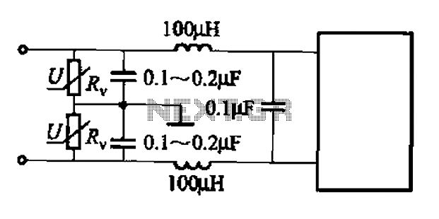
Common low-pass filter circuit b
A common low-pass filter circuit is illustrated. Figures (a) to (c) demonstrate its ability to suppress high-frequency interference, while Figure (b) shows a varistor that can absorb lightning surge voltage. Figure (d) indicates the circuit's capability to suppress low interference,...
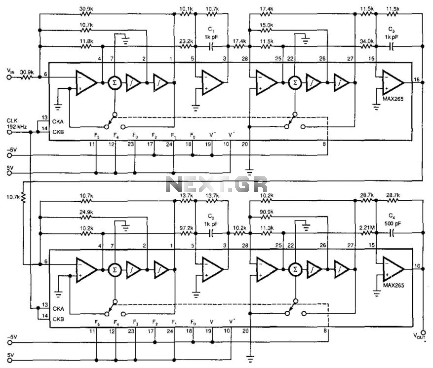
Antialiasing And Sync-Compensation Filter
Two dual-biquad filter chips and some external components form a multipurpose filter to reconstruct D/A converter signals. Connected to a converter's output, the filter provides antialiasing, reduces the D/A converter's quantization noise, and compensates for the "sync" function (attenuation). The...