


Circuit having a high school bass tone function
#bass tone
#pitch analysis
#buffer
#preamp
#control circuit
#audio processing
#signal conditioning
#sound design
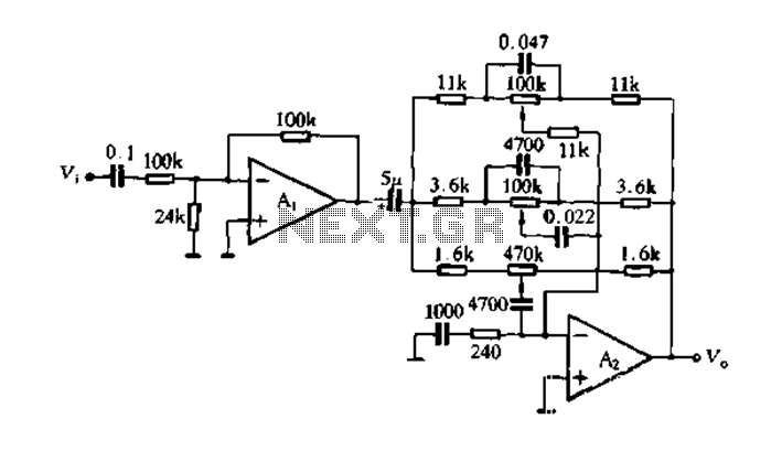
Description: Figure 4-7 illustrates the pitch analysis based on the relationship derived from the design calculation of the control circuit. In this setup, Ai serves as a buffer for the large stage, thereby alleviating the load on the preamplifier output. The circuit features a low corner frequency of 30 Hz and a high corner frequency of 1 kHz, with a control range of 20 dB. This design not only incorporates an operational amplifier equipped with high bass control tone circuit functions but also includes a high school bass control tone system function. The actual circuit is depicted in Figure 4-9.
The circuit described operates within a defined frequency range, facilitating effective audio processing. The low corner frequency of 30 Hz indicates that the circuit can handle deep bass signals, making it suitable for applications requiring low-frequency response, such as subwoofers or audio systems designed for bass-heavy music genres. The high corner frequency of 1 kHz establishes an upper limit for the circuit's operation, ensuring that it effectively filters out unwanted high-frequency noise while maintaining the integrity of the audio signal within the desired range.
The control range of 20 dB provides significant flexibility in adjusting the bass response, allowing for customization based on user preferences or specific audio environments. The operational amplifier utilized in this circuit is crucial for achieving the desired amplification and tone control, ensuring that the audio signals are processed with minimal distortion and optimal fidelity.
The buffer stage, represented by Ai, plays a vital role in this design by isolating the preamplifier output from the subsequent stages of the circuit. This isolation is essential for preventing loading effects that could degrade the signal quality. By reducing the burden on the preamplifier, the buffer allows for improved overall performance and stability of the audio system.
In summary, the circuit design integrates advanced audio processing capabilities with a focus on low-frequency performance and user control, making it an effective solution for enhancing audio quality in various applications. The schematic in Figure 4-9 provides a visual representation of the circuit, detailing the connections and components involved in achieving the specified functionality.Figure 4-7 pitch analysis using the relation obtained above design calculation control circuit, where Ai is a buffer to put the big stage, to reduce the burden preamp output. L ow-corner frequency of the circuit is 30Hz, high frequency corner frequency of 1kHz, the control range of 20dBo not only to design an operational amplifier having a high bass control tone circuit functions, but also to design a high school bass control tone system function the control circuit, the actual circuit shown in Figure 4-9.
The circuit described operates within a defined frequency range, facilitating effective audio processing. The low corner frequency of 30 Hz indicates that the circuit can handle deep bass signals, making it suitable for applications requiring low-frequency response, such as subwoofers or audio systems designed for bass-heavy music genres. The high corner frequency of 1 kHz establishes an upper limit for the circuit's operation, ensuring that it effectively filters out unwanted high-frequency noise while maintaining the integrity of the audio signal within the desired range.
The control range of 20 dB provides significant flexibility in adjusting the bass response, allowing for customization based on user preferences or specific audio environments. The operational amplifier utilized in this circuit is crucial for achieving the desired amplification and tone control, ensuring that the audio signals are processed with minimal distortion and optimal fidelity.
The buffer stage, represented by Ai, plays a vital role in this design by isolating the preamplifier output from the subsequent stages of the circuit. This isolation is essential for preventing loading effects that could degrade the signal quality. By reducing the burden on the preamplifier, the buffer allows for improved overall performance and stability of the audio system.
In summary, the circuit design integrates advanced audio processing capabilities with a focus on low-frequency performance and user control, making it an effective solution for enhancing audio quality in various applications. The schematic in Figure 4-9 provides a visual representation of the circuit, detailing the connections and components involved in achieving the specified functionality.Figure 4-7 pitch analysis using the relation obtained above design calculation control circuit, where Ai is a buffer to put the big stage, to reduce the burden preamp output. L ow-corner frequency of the circuit is 30Hz, high frequency corner frequency of 1kHz, the control range of 20dBo not only to design an operational amplifier having a high bass control tone circuit functions, but also to design a high school bass control tone system function the control circuit, the actual circuit shown in Figure 4-9.
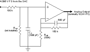
Signal Conditioning Analog Front-end for Microcontrollers
The I/O board incorporates 16-bit resolution voltage analog inputs and outputs, along with a 4-20mA current loop transmitter and receiver for microcontroller applications. The document discusses amplifier circuits and schematics, including a signal conditioning variable gain amplifier, analog filter, and...
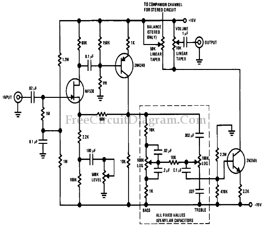
Low Cost High Level Preamp and Tone Control Circuit
To achieve optimal performance as a low noise, high input impedance device, the preamplifier and tone control utilize JFET technology. The circuit is designed to minimize harmonic distortion levels.
The use of Junction Field Effect Transistors (JFETs) in the preamplifier and...
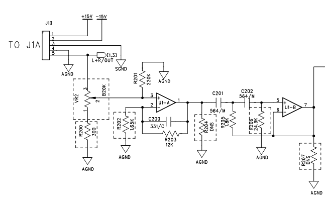
Noisy Pot-like noise in preamp circuit
A preamp circuit in a powered subwoofer is producing a static or popping noise, reminiscent of a scratchy or dirty sound.
The preamp circuit in question is crucial for amplifying low-level audio signals before they are sent to the power amplifier...
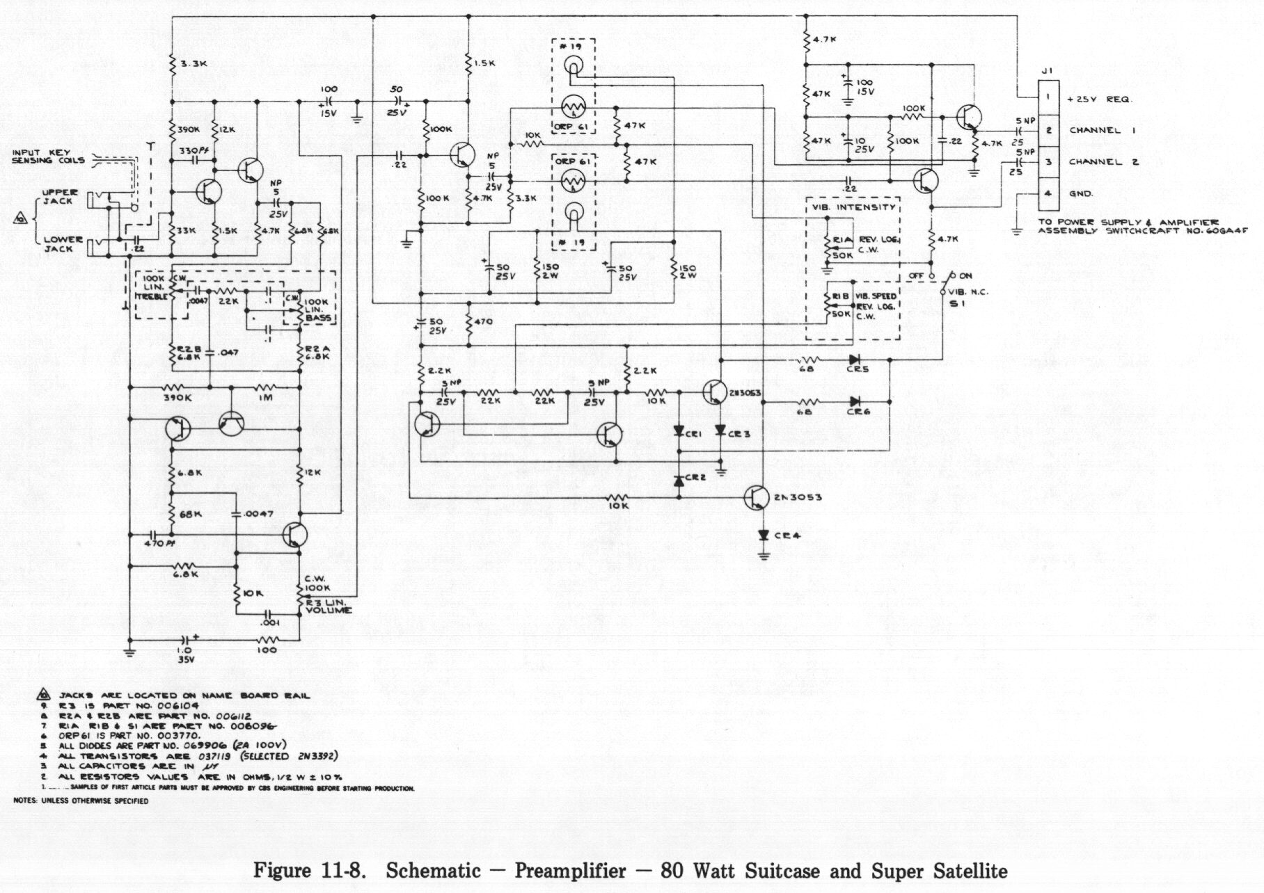
Fender rhodes peterson vibrato preamp
There is significant hiss produced by the circuit. Reducing the treble knob alleviates this issue, although it diminishes treble response. The hiss becomes more pronounced when the vibrato circuit is activated. After these observations, the board was re-capped according to...
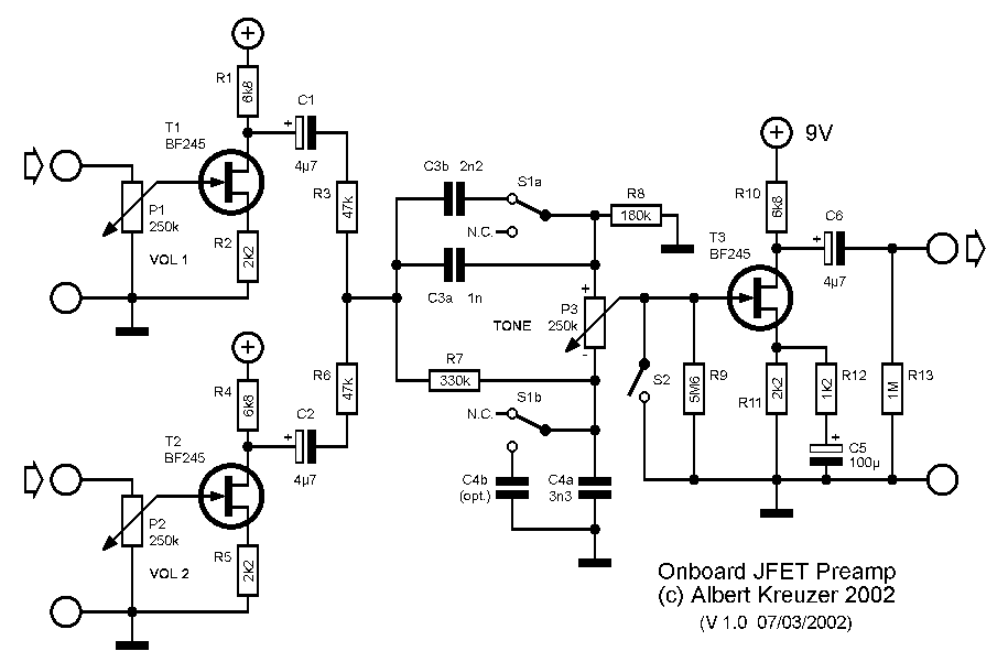
preamp onboard
Following the unexpectedly significant success of a JFET bass preamp, an onboard version was developed for a Jazz Bass-like instrument. The design incorporates three controls, potentially utilizing push-pull pots to include additional switches. The intention was to maintain the original...
preamp
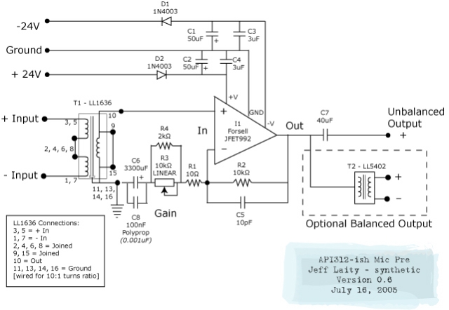
This is the final microphone preamplifier schematic. The input phase switch and phantom power circuit are not included, but they are based on the Jensen microphone input design AS016.
The microphone preamplifier schematic serves as a crucial component in audio...
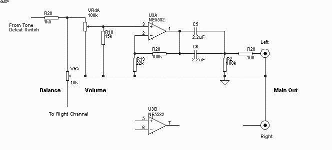
Simple High Quality Preamp For Hi-Fi
The new version has PCBs available and is recommended for optimal sound quality. For those needing tone controls, Project 97 is an excellent choice, offering superior sound quality and tone control features. While preamps have been widely discussed, they are...
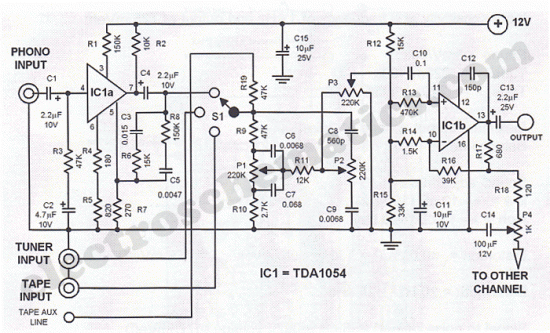
Hi Fi Stereo Preamp Circuit
The first half of the circuit (IC1a) features an input sensitivity of 3 mV and includes a frequency correction network consisting of capacitors C5, C3, and resistors R6 and R8. The bass signal from the phono input is amplified, while...
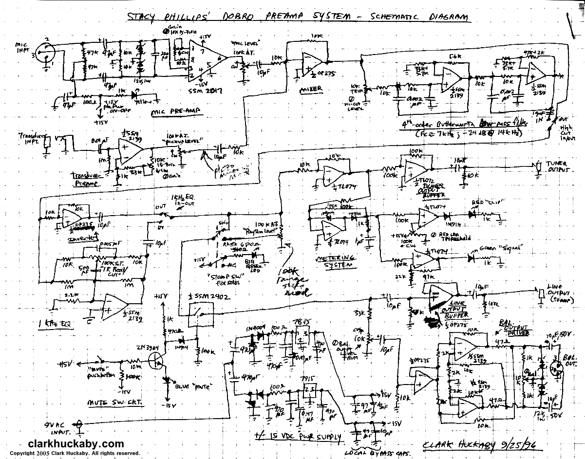
Preamp Mixer Stomp-Box for Dobro Guitar
A stomp-box was designed and built for Grammy-winning resophonic guitar player Stacy Phillips. He typically uses two transducers on his Dobro-style instruments: a piezo element mounted internally and a gooseneck-mounted electret microphone positioned approximately one inch above the resonator cover....