


Circuit Power audio Amplifier with TDA2030 2.1 Chanell 3 x 18 Watts Subwoofer Complete With PCB suggestion and power supply
#TDA2030
#amplifier
#subwoofer
#stereo
#power supply
#PCB
#bass amplifier
#audio system
#symmetric power supply
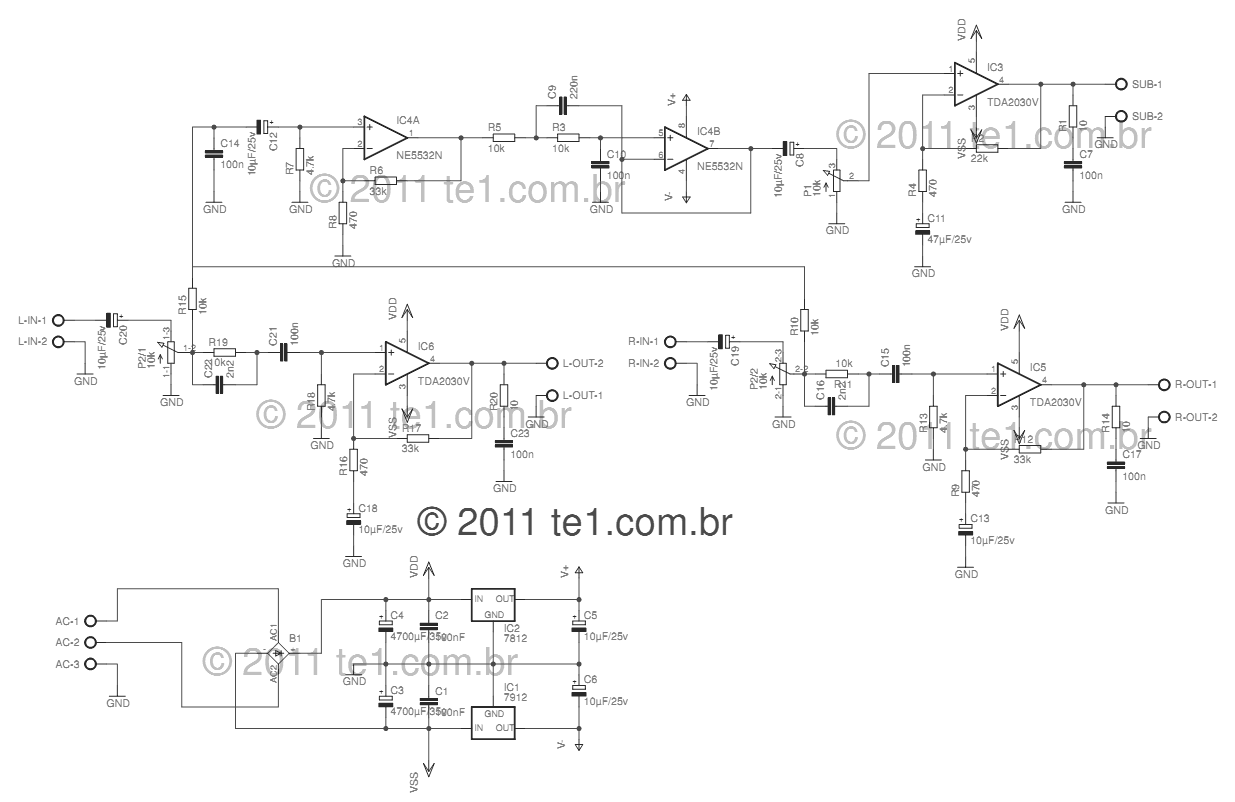
Description: This circuit is a complete application for a 2.1 amplifier system, consisting of two satellite speakers powered by a TDA2030 and one subwoofer. This 2.1 system is commonly utilized in commercial applications as an amplifier for computers, enhancing audio performance with a stereo amplifier and a bass amplifier (subwoofer). The power supply is of a symmetric type, using a transformer rated for either 110 or 220 volts with dual secondary outputs of 12 volts and 3A current. It is advisable to incorporate a fuse and a switch before the transformer. The circuit includes a bridge rectifier (B1) rated for at least 100 volts and 4A, such as the GBU606. The filtering circuit consists of capacitors C1, C2, C3, and C4, with electrolytic capacitors having values around 4700 µF. The power supply for the operational amplifier high-pass filter utilizes three-terminal integrated circuits, 7812 and 7912. The left and right channels are identical; for the left channel, LIN serves as the audio input jack, coupled through capacitor C20 to a dual potentiometer for volume adjustment, which controls both channels simultaneously. Resistor R19 and capacitor C22 enhance the treble signal. Capacitor C21 couples the signal to the TDA2030 (CI6), and the amplified audio output is taken from pin 4 of the integrated circuit. Resistors R7 and R9 provide feedback, allowing for gain adjustment by changing the value of R7. Resistors R20 and C23 form a compensation network for the speakers. The subwoofer signal is derived from the left and right channels through resistors R15 and R10, decoupled by capacitor C12, and sent to operational amplifier IC4A (NE5532), which acts as a pre-amplifier to boost the signal by six times, determined by resistors R6 and R8. Components C9, C10, and R10 create a low-pass filter, calculated for a cutoff frequency of 200Hz. After passing through IC4B, the low-frequency audio is adjusted by potentiometer P1 to set the volume level before being forwarded to IC3, which functions as the subwoofer amplifier, operating on principles similar to those of the satellite amplifiers.
This 2.1 amplifier circuit is designed to provide a balanced audio experience, effectively separating low and high frequencies for optimal sound reproduction. The use of the TDA2030 integrated circuit for satellite speakers ensures efficient amplification with low distortion, making it suitable for various applications including home audio systems and computer setups. The power supply design, featuring a dual secondary transformer and robust filtering capacitors, ensures stable operation and minimizes noise, enhancing overall audio quality. The inclusion of feedback and compensation networks allows for fine-tuning of the amplifier's performance, accommodating different speaker configurations and user preferences. The NE5532 operational amplifier, known for its low noise and high gain characteristics, further improves the audio signal, ensuring that both satellite and subwoofer outputs are clear and powerful. This circuit exemplifies a well-rounded approach to audio amplification, combining reliability, efficiency, and high fidelity.This circuit is a complete application is 2. 1 amp, two satellite speakers for TDA and one for the subwoofer, making the 2. 1 system, widely used in commercial applications as an amplifier for computers, which may give an increased in its audio system with a stereo amplifier + bass amplifier (subwoofer). The power supply is of symmetric type, using a transformer, 110 or 220 with dual secondary 12 volts and 3A current. I recommend using a fuse and a switch before the transformer. B1 is a bridge rectifier least 100 volts / 4 A, an example that can be used is GBU606, the filtering circuit is formed of the capacitors C1, C2, C3 and C4, the electrolytes can have values from 4700 F. The power supply for the op amp Highpass filter, is used three terminal integrated circuits 7812 and 7912.
The left and right channels give exactly the same, let`s see how the left channel: LIN is the audio input jack, which is coupled by C20 to the pot volume adjustment, it is a double pot, and set the two channels simultaneously. R19/C22, helps to improve the signal of the treble. The capacitor C21 couples the signal to CI6 TDA2030, after amplified audio output is pin 4 of integrated.
The resistor R7 and R9 are responsible for feedback, so by changing the value of R7 can increase or decrease the gain of the amplifier. R20 and C23 form the compensation network for the speakers. The signal comes from the subwoofer to the left and right channels by resistors R15 and R10 being decoupled by capacitor C12, is applied in the operational amplifier 1 IC4A NE5532, which forms a pre-amplifier to boost the signal by 6 times.
Determined by R6/R8 resistor. The components C9, C10 and R10 form a low pass filter in this case is calculated to 200Hz. After leaving IC4B the low frequency audio through the potentiometer P1 that makes the volume level, then forwarded to IC3 is what makes the subwoofer amplifier, the operating principle is the same as satellite amplifiers.
This 2.1 amplifier circuit is designed to provide a balanced audio experience, effectively separating low and high frequencies for optimal sound reproduction. The use of the TDA2030 integrated circuit for satellite speakers ensures efficient amplification with low distortion, making it suitable for various applications including home audio systems and computer setups. The power supply design, featuring a dual secondary transformer and robust filtering capacitors, ensures stable operation and minimizes noise, enhancing overall audio quality. The inclusion of feedback and compensation networks allows for fine-tuning of the amplifier's performance, accommodating different speaker configurations and user preferences. The NE5532 operational amplifier, known for its low noise and high gain characteristics, further improves the audio signal, ensuring that both satellite and subwoofer outputs are clear and powerful. This circuit exemplifies a well-rounded approach to audio amplification, combining reliability, efficiency, and high fidelity.This circuit is a complete application is 2. 1 amp, two satellite speakers for TDA and one for the subwoofer, making the 2. 1 system, widely used in commercial applications as an amplifier for computers, which may give an increased in its audio system with a stereo amplifier + bass amplifier (subwoofer). The power supply is of symmetric type, using a transformer, 110 or 220 with dual secondary 12 volts and 3A current. I recommend using a fuse and a switch before the transformer. B1 is a bridge rectifier least 100 volts / 4 A, an example that can be used is GBU606, the filtering circuit is formed of the capacitors C1, C2, C3 and C4, the electrolytes can have values from 4700 F. The power supply for the op amp Highpass filter, is used three terminal integrated circuits 7812 and 7912.
The left and right channels give exactly the same, let`s see how the left channel: LIN is the audio input jack, which is coupled by C20 to the pot volume adjustment, it is a double pot, and set the two channels simultaneously. R19/C22, helps to improve the signal of the treble. The capacitor C21 couples the signal to CI6 TDA2030, after amplified audio output is pin 4 of integrated.
The resistor R7 and R9 are responsible for feedback, so by changing the value of R7 can increase or decrease the gain of the amplifier. R20 and C23 form the compensation network for the speakers. The signal comes from the subwoofer to the left and right channels by resistors R15 and R10 being decoupled by capacitor C12, is applied in the operational amplifier 1 IC4A NE5532, which forms a pre-amplifier to boost the signal by 6 times.
Determined by R6/R8 resistor. The components C9, C10 and R10 form a low pass filter in this case is calculated to 200Hz. After leaving IC4B the low frequency audio through the potentiometer P1 that makes the volume level, then forwarded to IC3 is what makes the subwoofer amplifier, the operating principle is the same as satellite amplifiers.

How to Increase TDA2030 Amplifier Gain PCB
The TDA 2030 is a widely used 14W audio power amplifier monolithic integrated circuit in a Pentawatt package, intended for use as a low-frequency Class AB amplifier. Some home theater prototypes utilize the TDA 2030 as a low-frequency subwoofer amplifier....
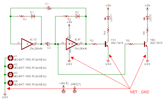
Board making technique
When designing a printed circuit board (PCB), a technique is employed to create a broad grounding pattern separate from the signal and power patterns. This approach is particularly useful for high-frequency circuits or when attempting to mitigate external noise interference....
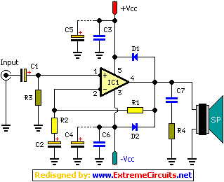
TDA2030 18W + 18W Stereo Hi-Fi Audio Amplifier circuit and explanation
A 2 x 18W Hi-Fi Stereo Power Amplifier is designed using two TDA2030 integrated circuits (ICs). This amplifier features good input sensitivity, low distortion, stable operation, and comprehensive protection against overloads and output short-circuits. It can serve as a booster...
Switching Regulator Circuit
This example presents a switch DC regulated power supply circuit designed for buck-mode +5V applications. It consists of a power supply circuit, an impulsator, a voltage sampling or pulse width modulation circuit, and a buffering driver circuit, as illustrated in...
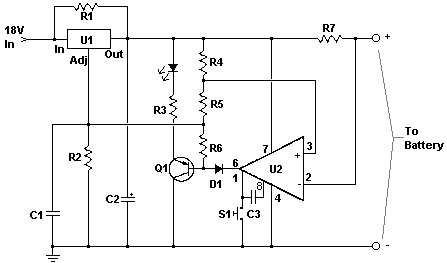
car battery charger circuit
The circuit is designed to be powered directly by a power supply, which is why it does not include a transformer, rectifier, or filter capacitors in the schematic. However, these components can be added if desired. To operate the circuit,...
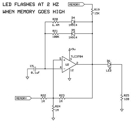
markII
The following circuits are presented in a logical order from initial power-up to the additional features incorporated at the end of the project. A less organized version of the Mark II design exists, but this is the sanitized and organized...
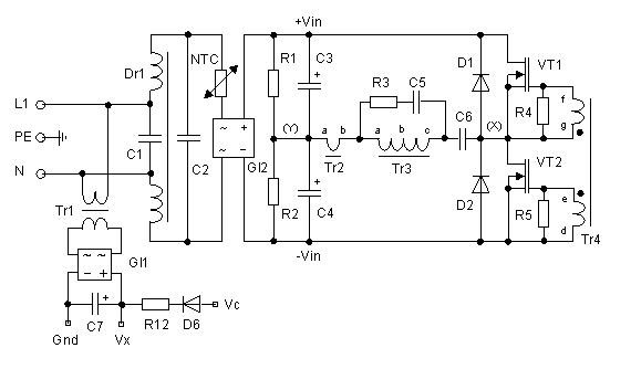
250 Watt PC power Supply
Up to 10 A continuous output current, or operation with 50 % ESD and 18 A peak current are possible without a fan if sufficient natural air flow is present and the ambient temperature does not exceed 30 °C. A...
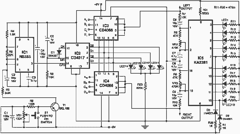
Stereo channel controller
The add-on circuit presented here is useful for stereo systems. This circuit has provision for connecting stereo outputs from four different sources/channels as inputs and only one of them is selected/connected to the output at any one time. When power...
printed circuit board pcb etching
This text assumes some prior knowledge of PCB etching methods and recounts an experience with the toner transfer technique. For those unfamiliar with the method, additional research may be necessary. The process of constructing a circuit on protoboard is relatively...