


Condenser Pre Amplifier LM 1458
#LM1458
#op-amp
#condenser microphone
#pre-amplifier
#audio signal
#variable output
#dual op amp
#6-9V supply
#microphone level
#signal amplification
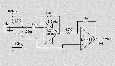
Description: This circuit utilizes an LM1458 dual operational amplifier integrated circuit (IC) to amplify audio signals from a condenser microphone. The amplified output allows the microphone to interface with devices that typically do not accept microphone-level signals. The circuit operates on a power supply ranging from 6 to 9 volts. The output level of the microphone amplifier can be adjusted by connecting a 10k ohm potentiometer. Additionally, the circuit's gain can be increased by modifying the resistor value of 47k ohms, depending on the input sensitivity requirements of the main amplifier system. It is recommended that the microphone be enclosed in a small round housing.
The LM1458 is a dual operational amplifier that is well-suited for audio applications due to its low noise and high gain characteristics. In this circuit, one of the op-amps is configured as a non-inverting amplifier, which provides a high input impedance to accommodate the low-level signal from the condenser microphone. The gain of the amplifier can be set using the feedback resistor (47k ohms) and the input resistor (the potentiometer), allowing for flexibility in sensitivity based on the requirements of the downstream audio processing equipment.
The power supply for this circuit should be stable and within the specified range of 6 to 9 volts to ensure optimal performance of the LM1458. The choice of a potentiometer for output adjustment allows for real-time control over the microphone's volume level, making it suitable for various applications such as public speaking, musical performances, or recording setups.
To enhance the performance of the microphone, proper housing is essential. A small round enclosure not only protects the microphone from environmental factors but also helps reduce handling noise and unwanted vibrations. The enclosure should be designed to minimize acoustic interference while allowing sound waves to reach the microphone effectively.
In summary, this circuit provides a practical solution for amplifying microphone signals, enabling compatibility with devices not designed for low-level audio inputs. The adjustable gain and careful design considerations make it a versatile choice for audio applications.Using a LM1458 dual op amp IC. The circuit takes the audio signal rom the condenser microphone and amplifier it, so you can use the microphone as the input to some device which wouldn`t normally accept microphone level signals. The circuit requires a 6-9 volt supply. Output of the microphone amplifier can be made variable by connecting a 10k © po tentiometer. Circuit`s gain can be increased by men perbesar the value of 47K, depending on the input sensitivity of the main amplifier system. The microphone should be housed in a small round enclosure.
The LM1458 is a dual operational amplifier that is well-suited for audio applications due to its low noise and high gain characteristics. In this circuit, one of the op-amps is configured as a non-inverting amplifier, which provides a high input impedance to accommodate the low-level signal from the condenser microphone. The gain of the amplifier can be set using the feedback resistor (47k ohms) and the input resistor (the potentiometer), allowing for flexibility in sensitivity based on the requirements of the downstream audio processing equipment.
The power supply for this circuit should be stable and within the specified range of 6 to 9 volts to ensure optimal performance of the LM1458. The choice of a potentiometer for output adjustment allows for real-time control over the microphone's volume level, making it suitable for various applications such as public speaking, musical performances, or recording setups.
To enhance the performance of the microphone, proper housing is essential. A small round enclosure not only protects the microphone from environmental factors but also helps reduce handling noise and unwanted vibrations. The enclosure should be designed to minimize acoustic interference while allowing sound waves to reach the microphone effectively.
In summary, this circuit provides a practical solution for amplifying microphone signals, enabling compatibility with devices not designed for low-level audio inputs. The adjustable gain and careful design considerations make it a versatile choice for audio applications.Using a LM1458 dual op amp IC. The circuit takes the audio signal rom the condenser microphone and amplifier it, so you can use the microphone as the input to some device which wouldn`t normally accept microphone level signals. The circuit requires a 6-9 volt supply. Output of the microphone amplifier can be made variable by connecting a 10k © po tentiometer. Circuit`s gain can be increased by men perbesar the value of 47K, depending on the input sensitivity of the main amplifier system. The microphone should be housed in a small round enclosure.
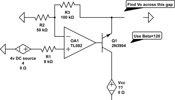
op amp Find Vo in an op-amp transistor circuit
The voltage measured at 12V after the emitter is perplexing, especially when the output from the op-amp is +15V, suggesting a 3V drop across the transistor. This raises questions about the expected gain of 2, which would imply an output...
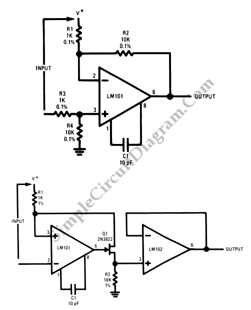
Op-Amp Application: Level Shifting Amplifier
In linear equipment design, it is sometimes necessary to take a voltage that is referenced to a certain DC level and generate an amplified output that is also referenced.
In linear circuit design, the process of amplifying a voltage that is...

High Voltage AC Calibrator Circuit Using Op Amp
This is an application circuit for calibration known as a high voltage AC calibrator circuit. An essential aspect of sine wave oscillator design is the stable control of amplitude. This circuit not only stabilizes the amplitude through servo control but...

op amp A probably very easy Op-Amp Analysis
I have been measuring V_A = 15, which appears to be incorrect. Additionally, I believe V+ is equal to 0 since the node below the 3-ohm resistor is grounded. Assistance is needed to begin solving this. Initially, I set V+...
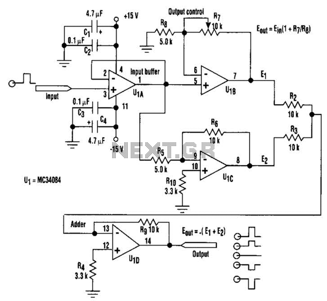
Polarity Gain Adjustment Circuit
By adjusting one potentiometer, the output of this circuit can be varied from a positive version of the input signal, smoothly transitioning through zero output, and then to a negative version of the input. For instance, if the input signal...
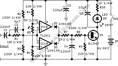
Audio Signal Clipping Indicator
A window comparator formed by two operational amplifiers packaged into IC1 is the heart of the circuit below. With this technique, we can detect precisely and symmetrically.
The window comparator circuit utilizes two operational amplifiers (op-amps) configured to create a defined...
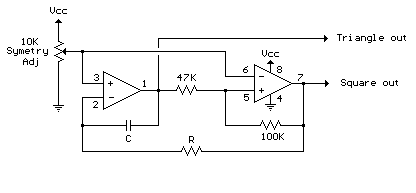
Audio Triangle Square Wave Generator Using Op-Amp
The circuit illustrates a straightforward triangle and square wave generator utilizing a common dual operational amplifier, the LM1558, capable of producing very low frequencies around 10 kHz. The time interval for one half-cycle is approximately determined by the product of...
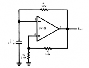
The Universal Linear Component
Operational amplifiers are the simplest and most effective means of executing a variety of linear functions, ranging from basic amplification to intricate analog computations.
Operational amplifiers (op-amps) are versatile components widely utilized in electronic circuits for various applications. These devices can...
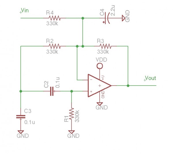
Karplus Strong Opamp Circuit
It is essentially an all-pass filter with two additional components: a capacitor and a resistor, which produces percussion sounds. A schematic of the unmodified all-pass filter circuit, a waveform captured via Audacity, and a short audio sample featuring a drum...