


Converting an EV PL-76 or 1776 microphone to p48 powering
#microphone
#P48 powering
#zener diode
#electrolytic capacitor
#vectorboard
#battery compartment
#resistors
#audio equipment
#modification
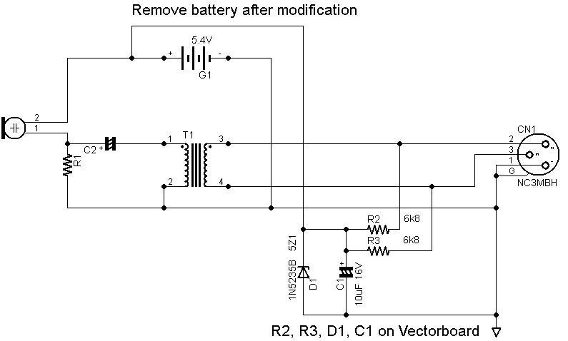
Description: The resistors may be rated at 1/8 watt. The zener diode can be either a 250 mW or a 1W component (the part number will differ). The electrolytic capacitor is a standard type, and its value can vary (larger capacitance and higher voltage ratings are acceptable), but it must ultimately fit within the battery compartment. A piece of vectorboard should be cut to fit across the flat surfaces of the battery compartment. Tin snips are suitable for this task. If tin snips are unavailable, the board can be scored by dragging a sharp knife across the perforations several times, followed by flexing the board at the cut marks to facilitate breaking along the scored line. The circuit should be built on the vectorboard and secured with tape. To construct the circuit using vectorboard, insert the leads of components through the board and bend them flat against the surface, resembling a printed circuit board layout. The leads of different components can be laid across one another and soldered together. Access to the connector is necessary. The locking screw at the end of the microphone should be located and turned counterclockwise to loosen it. Since this is a Switchcraft insert, the screw retracts inside the connector, allowing for one of the pins to be grasped with pliers and gently pulled loose to avoid damaging the attached wires. The wires leading to the vectorboard should then be soldered to pins 1, 2, and 3. Afterward, the wires should be threaded back into the battery compartment, and the connector insert should be reinserted. Finally, the connector must be secured by turning the insert screw clockwise.
The circuit described involves several key components that must be carefully integrated for proper functionality. Resistors rated at 1/8 watt are adequate for most applications, ensuring they can handle the current without overheating. The zener diode's power rating, whether 250 mW or 1W, should be selected based on the specific voltage regulation requirements of the circuit. The electrolytic capacitor’s flexibility in capacitance and voltage rating allows for optimization based on available space and desired performance, but it is crucial that its dimensions allow it to fit within the designated battery compartment.
To prepare the vectorboard, precise cutting is essential to ensure a snug fit within the battery compartment. The use of tin snips or a scoring technique provides options for achieving the desired dimensions. Once the vectorboard is prepared, the assembly process involves inserting component leads through the board and bending them to create a compact layout, similar to that of a printed circuit board. This method enhances the reliability of solder joints and minimizes the risk of short circuits.
Soldering requires careful attention to detail, particularly when connecting multiple component leads. Ensuring that leads do not cross inappropriately and that solder joints are clean and secure is vital for circuit integrity. Accessing the connector is a critical step in this process. The locking screw mechanism of the Switchcraft insert is designed for secure connection, and care should be taken to avoid damaging the pins during disassembly. Proper soldering of the wires to the vectorboard is necessary to maintain connectivity and functionality of the circuit.
Once the circuit is fully assembled and the connector is reinserted, securing the locking screw ensures that the connection remains stable during operation. This comprehensive approach to building the circuit on vectorboard allows for a reliable and efficient design that meets the specified requirements while fitting within the physical constraints of the battery compartment.The resistors could be 1/8w, The zener diode could be a 250mW part, or it could be a 1W part (1N number will be different). The electrolytic capacitor is plain vanilla, and the value can deviate (larger is ok, higher voltage is ok), but when it`s all done, it has to fit inside the battery compartment.
Cut a piece of vectorboard that fits across the flats of the battery compartment. Tin snips work just fine. Lacking that, you can score the board by dragging a sharp knife across the perfs several times, then flex the board against the cut marks to encourage it to break along the scoring. Build the circuit on the vectorboard. Fasten with tape. To build a circuit using Vectorboard, push the leads through the board, then bend them flat against the board, bending them to approximate a printed circuit board.
Lay the leads of different components across each other and solder. You`ll need to access the connector. Locate the connector`s locking screw at the end of the microphone. Turn the screw counterclockwise to loosen it. This is a Switchcraft insert, so the screw retracts INSIDE the connector, and you can now grab one of the pins with a pair of pliers and gently pull it loose (lest you break the wires attached to it). Now you can solder the wires going to the vectorboard to pins 1, 2, and 3. Then thread the wires back into the battery compartment and reinsert the connector insert. Remember to lock the connector in place by turning the insert screw clockwise.
The circuit described involves several key components that must be carefully integrated for proper functionality. Resistors rated at 1/8 watt are adequate for most applications, ensuring they can handle the current without overheating. The zener diode's power rating, whether 250 mW or 1W, should be selected based on the specific voltage regulation requirements of the circuit. The electrolytic capacitor’s flexibility in capacitance and voltage rating allows for optimization based on available space and desired performance, but it is crucial that its dimensions allow it to fit within the designated battery compartment.
To prepare the vectorboard, precise cutting is essential to ensure a snug fit within the battery compartment. The use of tin snips or a scoring technique provides options for achieving the desired dimensions. Once the vectorboard is prepared, the assembly process involves inserting component leads through the board and bending them to create a compact layout, similar to that of a printed circuit board. This method enhances the reliability of solder joints and minimizes the risk of short circuits.
Soldering requires careful attention to detail, particularly when connecting multiple component leads. Ensuring that leads do not cross inappropriately and that solder joints are clean and secure is vital for circuit integrity. Accessing the connector is a critical step in this process. The locking screw mechanism of the Switchcraft insert is designed for secure connection, and care should be taken to avoid damaging the pins during disassembly. Proper soldering of the wires to the vectorboard is necessary to maintain connectivity and functionality of the circuit.
Once the circuit is fully assembled and the connector is reinserted, securing the locking screw ensures that the connection remains stable during operation. This comprehensive approach to building the circuit on vectorboard allows for a reliable and efficient design that meets the specified requirements while fitting within the physical constraints of the battery compartment.The resistors could be 1/8w, The zener diode could be a 250mW part, or it could be a 1W part (1N number will be different). The electrolytic capacitor is plain vanilla, and the value can deviate (larger is ok, higher voltage is ok), but when it`s all done, it has to fit inside the battery compartment.
Cut a piece of vectorboard that fits across the flats of the battery compartment. Tin snips work just fine. Lacking that, you can score the board by dragging a sharp knife across the perfs several times, then flex the board against the cut marks to encourage it to break along the scoring. Build the circuit on the vectorboard. Fasten with tape. To build a circuit using Vectorboard, push the leads through the board, then bend them flat against the board, bending them to approximate a printed circuit board.
Lay the leads of different components across each other and solder. You`ll need to access the connector. Locate the connector`s locking screw at the end of the microphone. Turn the screw counterclockwise to loosen it. This is a Switchcraft insert, so the screw retracts INSIDE the connector, and you can now grab one of the pins with a pair of pliers and gently pull it loose (lest you break the wires attached to it). Now you can solder the wires going to the vectorboard to pins 1, 2, and 3. Then thread the wires back into the battery compartment and reinsert the connector insert. Remember to lock the connector in place by turning the insert screw clockwise.

Microphone Circuit Test Oscillator
This circuit is designed to be housed in a compact plastic or preferably metal enclosure, powered by a 9V battery. It features a level control, a male XLR connector (similar to those used in microphones), and a switch. The current...
microphone amplifier 20khz 12v
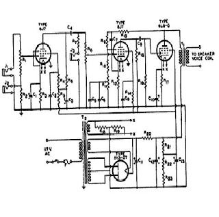
The signal from a microphone is too weak for a standard line input. This low-noise DC-coupled microphone amplifier provides a solution for anyone who wants to connect a microphone to a high-fidelity installation. As shown in the schematic diagram, a...
Sound card microphone
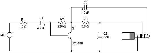
Most sound card microphone inputs require a minimum signal level of at least 10 millivolts, but some older 8-bit cards need as much as 100 millivolts. The typical impedance of the PC sound card microphone input is in the range...
The Synthetic Psychology of Sound Localization
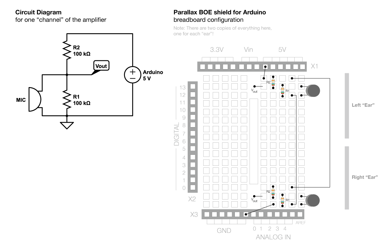
The voltage across the two pins of a microphone fluctuates based on the input sound. To amplify this signal for the Arduino to read it, a complex circuit is required. Initially, the voltage changes from the microphone are small (usually...
Simple Under-Voltage Cut-Out
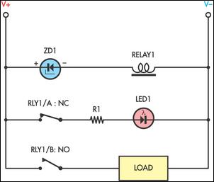
Sensitive low-current relay coils often operate at much lower voltages than their typical ratings. This can be undesirable in some applications, where low supply voltages can result in erratic system behavior. In some instances, this problem could be overcome simply...
simple mic preamp
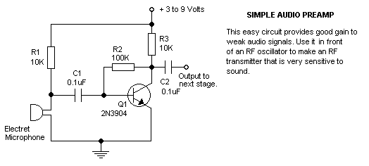
this is a very easy circuit to build - all parts can be found at the local electronics shop.
The described circuit is characterized by its simplicity and accessibility, making it an ideal project for beginners or those looking to quickly...
simple Sound Trigger
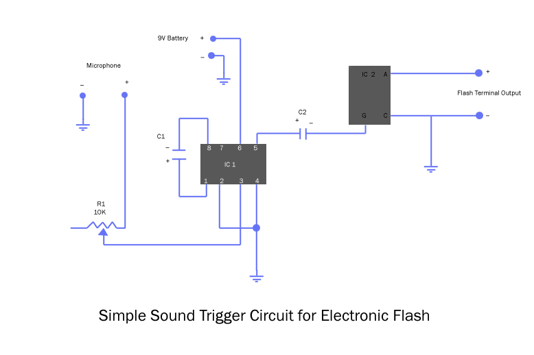
The microphone inputs connect to ground (-) and to the middle terminal of a 10K variable resistor (potentiometer), which serves as the sensitivity control. The output from the potentiometer is routed to pin 3 of the amplifier integrated circuit (IC),...
Dual-Mode Microphone Pre-Amplifier Schematic Diagram
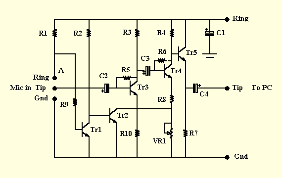
This is a microphone preamplifier designed for compatibility with a SoundBlaster AWE 64 sound card. It is also suitable for any compatible tag or PC audio input that provides a 5 Volt supply through a 2.2kΩ current-limiting resistor located at...
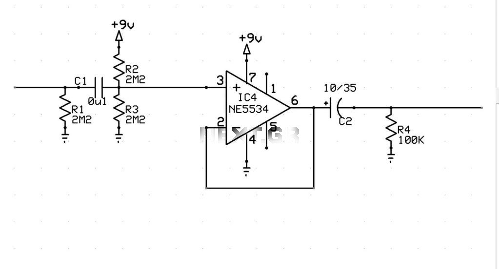
Microphone Preamp Buffer Help
A decision has been made to construct a microphone preamplifier and tone control circuit that was featured on another website. The equalization section is identical to the one used in the...
This microphone preamplifier and tone control circuit is designed to...