


Digital Guitar Tuner
#guitar tuner
#digital tuner
#LED indicator
#audio processing
#instrument tuning
#microphone input
#signal sampling
#frequency comparison
#musical instruments
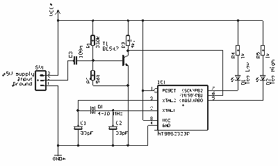
Description: The circuit is a simple, but accurate Digital Guitar Tuner. It samples the input, which can be directly from the mics of an electric guitar, or from a microphone, if you're using an acoustic guitar. It can of course also be used for tuning other instruments. The samples are then checked against stored values for the strings, and the two LEDs will show the tuning status - "Too Low", "Too High" or "In Tune" when both LEDs are lit.
The Digital Guitar Tuner circuit operates by utilizing a microcontroller or a dedicated frequency detection IC to analyze the frequency of the incoming audio signal. The circuit typically includes an audio input stage that may consist of an operational amplifier configured as a preamplifier to boost the signal from the guitar or microphone.
Once the signal is amplified, it is fed into an analog-to-digital converter (ADC) if a microcontroller is used, or directly to a frequency detection circuit. This component is responsible for determining the fundamental frequency of the audio signal, which corresponds to the pitch of the note being played.
The circuit is programmed with reference frequencies for standard guitar tuning (E2, A2, D3, G3, B3, E4) or other instruments as required. The detected frequency is compared against these stored values. If the detected frequency is lower than the reference frequency, one LED (indicating "Too Low") will illuminate. Conversely, if the detected frequency is higher, the other LED (indicating "Too High") will light up. When the detected frequency matches the reference frequency, both LEDs will illuminate, indicating that the instrument is in tune.
Additional features may include a display unit, such as a seven-segment display or an LCD, to provide a visual representation of the detected pitch and its deviation from the target frequency, enhancing user interaction. Power supply considerations for the circuit can range from battery operation to USB power, depending on the intended application and portability requirements.
Overall, the Digital Guitar Tuner circuit is a valuable tool for musicians, providing an accurate and easy-to-use solution for tuning a variety of stringed instruments.The circuit is a simple, but accurate Digital Guitar Tuner. It samples the input, which can be directly from the mics of an electric guitar, or from a microphone, it you`re using an acoustic guitar. It can ofcourse also be used for tuning other instruments. The samples are then checked against stored values for the strings, and the two LED`s will show the tuning status - "Too Low", "Too High" or "In Tune" when both LED`s are lit.
The Digital Guitar Tuner circuit operates by utilizing a microcontroller or a dedicated frequency detection IC to analyze the frequency of the incoming audio signal. The circuit typically includes an audio input stage that may consist of an operational amplifier configured as a preamplifier to boost the signal from the guitar or microphone.
Once the signal is amplified, it is fed into an analog-to-digital converter (ADC) if a microcontroller is used, or directly to a frequency detection circuit. This component is responsible for determining the fundamental frequency of the audio signal, which corresponds to the pitch of the note being played.
The circuit is programmed with reference frequencies for standard guitar tuning (E2, A2, D3, G3, B3, E4) or other instruments as required. The detected frequency is compared against these stored values. If the detected frequency is lower than the reference frequency, one LED (indicating "Too Low") will illuminate. Conversely, if the detected frequency is higher, the other LED (indicating "Too High") will light up. When the detected frequency matches the reference frequency, both LEDs will illuminate, indicating that the instrument is in tune.
Additional features may include a display unit, such as a seven-segment display or an LCD, to provide a visual representation of the detected pitch and its deviation from the target frequency, enhancing user interaction. Power supply considerations for the circuit can range from battery operation to USB power, depending on the intended application and portability requirements.
Overall, the Digital Guitar Tuner circuit is a valuable tool for musicians, providing an accurate and easy-to-use solution for tuning a variety of stringed instruments.The circuit is a simple, but accurate Digital Guitar Tuner. It samples the input, which can be directly from the mics of an electric guitar, or from a microphone, it you`re using an acoustic guitar. It can ofcourse also be used for tuning other instruments. The samples are then checked against stored values for the strings, and the two LED`s will show the tuning status - "Too Low", "Too High" or "In Tune" when both LED`s are lit.
Audio Beat Detect ?« Electronic Product Design
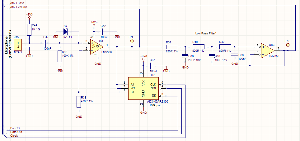
This circuit employs a digital potentiometer to enable the microcontroller to automatically adjust the circuit's gain according to the ambient audio volume. However, a standard potentiometer can be used if automatic adjustment is unnecessary. The low-pass filter design is based...
Guitar and bass tuner
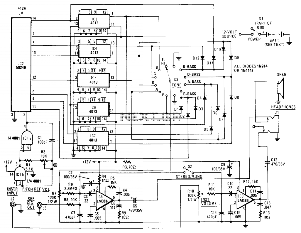
The core component of the circuit is IC2, a 50240 top-octave generator. This device utilizes a single input frequency to produce all twelve notes of the musical scale. The input signal is supplied by IC1, a 4001 quad 2-input NOR...
Audio Peak / Beat LED indicator
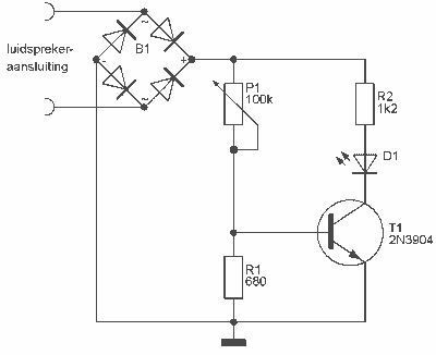
This indicator can be used, or see if your speakers can be damaged by the noise power. With P1 you can set the limit to which D1 LED lights. The pot is 100k here, you can even experiment with other...
ARRL Handbook Audio Intelligibility Enhancer
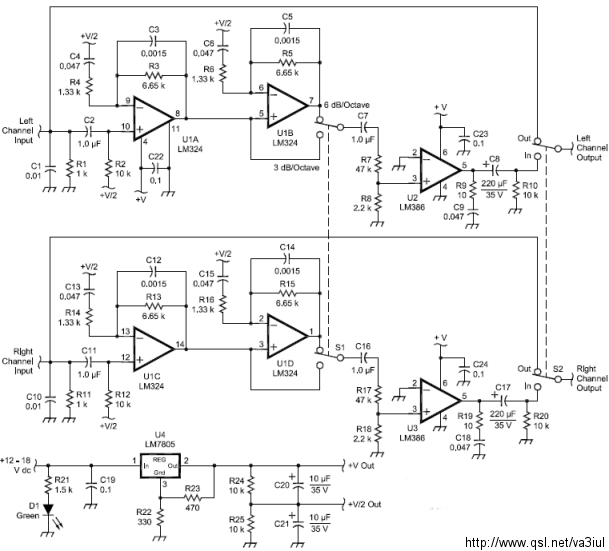
Assistance is sought for building the N4GG audio intelligibility enhancer project as detailed in the ARRL Handbook. A circuit board has been ordered from Far Circuits, but there are difficulties in sourcing the necessary components. Attempts have been made to...
Arduino Vocal Effects Box
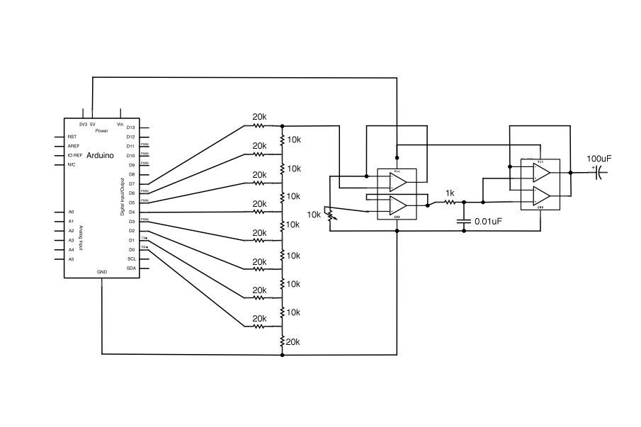
This Arduino-powered vocal effects box pitch shifts and distorts incoming audio signals to produce a wide variety of vocal effects. This project is an experiment with real-time digital signal processing using Arduino. It samples an incoming microphone signal at a...
4047/4066 audio slicer
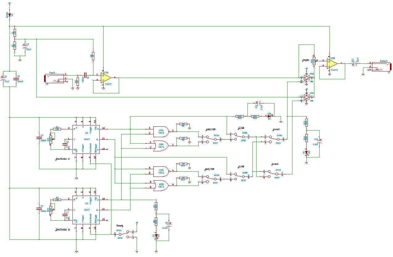
You need to connect pins 1 and 13 of the 4053 to the virtual ground rail (top of C4), not the circuit's 0V rail.
The CD4053 is a triple 2-channel analog multiplexer/demultiplexer integrated circuit, widely used for routing analog signals...

Central-image-canceller
The circuit is designed to eliminate the vocal portion of an audio signal while preserving the instrumental portion. It achieves this by mixing two channels that are 180° out of phase, allowing the signals that create the center-stereo image to...