


Doorbell Sound with CD4001 CD4060
#CD4001
#CD4060
#two-tone sound
#frequency division
#sound frequency generator
#audio signal
#doorbell
#switch
#frequency converter
#IC2
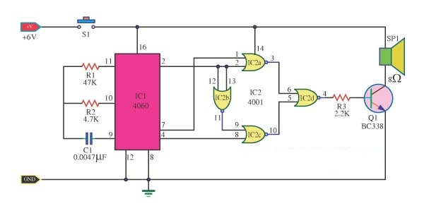
Description: The doorbell sound circuit produces a two-tone sound. The circuit operates with switch S1. The integrated circuit IC1 functions as a frequency division circuit and generates sound frequencies through components C1 and R1. The audio signal is transmitted from pin 7 and pin 4 of IC1 to pin 1 and pin 8 of IC2a and IC2c, respectively. IC2b serves as a frequency converter that controls IC2c. When the control signal is low, a frequency of 1.25 kHz is generated in IC2a. Simultaneously, when the control signal is high, IC2b generates a frequency of 300 Hz in IC2c. The output at pin 3 of IC2a remains low under these conditions, which allows for the production of tones from IC2a, IC2c, and IC2d. These signals are then sent to output transistors Q1, which act as switches and tone amplifiers, producing audible two-tone sounds. Resistor R3 functions as a volume control, allowing for adjustment of sound levels, with a power supply of 6 volts.
The doorbell sound circuit is designed to provide a distinct auditory signal through the use of frequency modulation and amplification techniques. The core of the circuit is centered around the frequency division capabilities of IC1, which generates the initial sound frequencies. The interaction between the various integrated circuits (IC2a, IC2b, and IC2c) is crucial for creating the two-tone effect.
IC1, acting as a frequency generator, utilizes the timing components C1 and R1 to define the generated frequencies. The output signals from IC1 are fed into the subsequent stages of the circuit, specifically IC2a and IC2c, which are configured to produce specific tones. The control signal from IC2b plays a pivotal role in determining which frequency is active at any given time, creating the alternating tones characteristic of a doorbell.
The use of output transistors Q1 enhances the audio signal by acting as amplifiers, ensuring that the sound produced is loud enough to be heard clearly. The inclusion of R3 as a variable resistor allows users to adjust the volume, providing flexibility in sound output according to user preference or environmental conditions. Powering the circuit with a 6-volt supply ensures adequate performance while maintaining safety and efficiency for typical doorbell applications.
Overall, this circuit exemplifies effective use of integrated components to achieve a functional and user-friendly doorbell sound system.The doorbell sound circuit was two-tone sound. With the switch S1. working of the circuit, IC1 is a frequency division circuit, and a sound frequency generator came out. by C1, R1 is the frequency generator. This audio signal from pin 7 and pin 4 to pin 1 and pin 8 of the IC2a, IC2c respectively. The IC2b of a frequency converter to control IC2c. Wh en control signal during the low (Low) 1. 25 kHz frequency coincides with IC2a. At same time, the control signal is in a high state IC2b (high), 300 Hz frequency IC2c parties. Output on pin 3 of low IC2a under the same conditions, production and IC2c IC2a IC2d. Which is sent to act as a signal and the output transistors act as switches Q1 and tones amplifiers. The can be heard as two strokes. R3 acts as a volume, add more value to make the softest sound, but softer, a source of 6 volts.
The doorbell sound circuit is designed to provide a distinct auditory signal through the use of frequency modulation and amplification techniques. The core of the circuit is centered around the frequency division capabilities of IC1, which generates the initial sound frequencies. The interaction between the various integrated circuits (IC2a, IC2b, and IC2c) is crucial for creating the two-tone effect.
IC1, acting as a frequency generator, utilizes the timing components C1 and R1 to define the generated frequencies. The output signals from IC1 are fed into the subsequent stages of the circuit, specifically IC2a and IC2c, which are configured to produce specific tones. The control signal from IC2b plays a pivotal role in determining which frequency is active at any given time, creating the alternating tones characteristic of a doorbell.
The use of output transistors Q1 enhances the audio signal by acting as amplifiers, ensuring that the sound produced is loud enough to be heard clearly. The inclusion of R3 as a variable resistor allows users to adjust the volume, providing flexibility in sound output according to user preference or environmental conditions. Powering the circuit with a 6-volt supply ensures adequate performance while maintaining safety and efficiency for typical doorbell applications.
Overall, this circuit exemplifies effective use of integrated components to achieve a functional and user-friendly doorbell sound system.The doorbell sound circuit was two-tone sound. With the switch S1. working of the circuit, IC1 is a frequency division circuit, and a sound frequency generator came out. by C1, R1 is the frequency generator. This audio signal from pin 7 and pin 4 to pin 1 and pin 8 of the IC2a, IC2c respectively. The IC2b of a frequency converter to control IC2c. Wh en control signal during the low (Low) 1. 25 kHz frequency coincides with IC2a. At same time, the control signal is in a high state IC2b (high), 300 Hz frequency IC2c parties. Output on pin 3 of low IC2a under the same conditions, production and IC2c IC2a IC2d. Which is sent to act as a signal and the output transistors act as switches Q1 and tones amplifiers. The can be heard as two strokes. R3 acts as a volume, add more value to make the softest sound, but softer, a source of 6 volts.
Announcer DoorBell
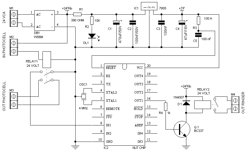
M1 is a clamp connected to the 24V (dc or ac) power from the gate opener. The diode bridge rectifies the alternate voltage (should the opener use dc current, it merely adjusts the positive and negative rail to match circuit...
Percussion electronic doorbell 1
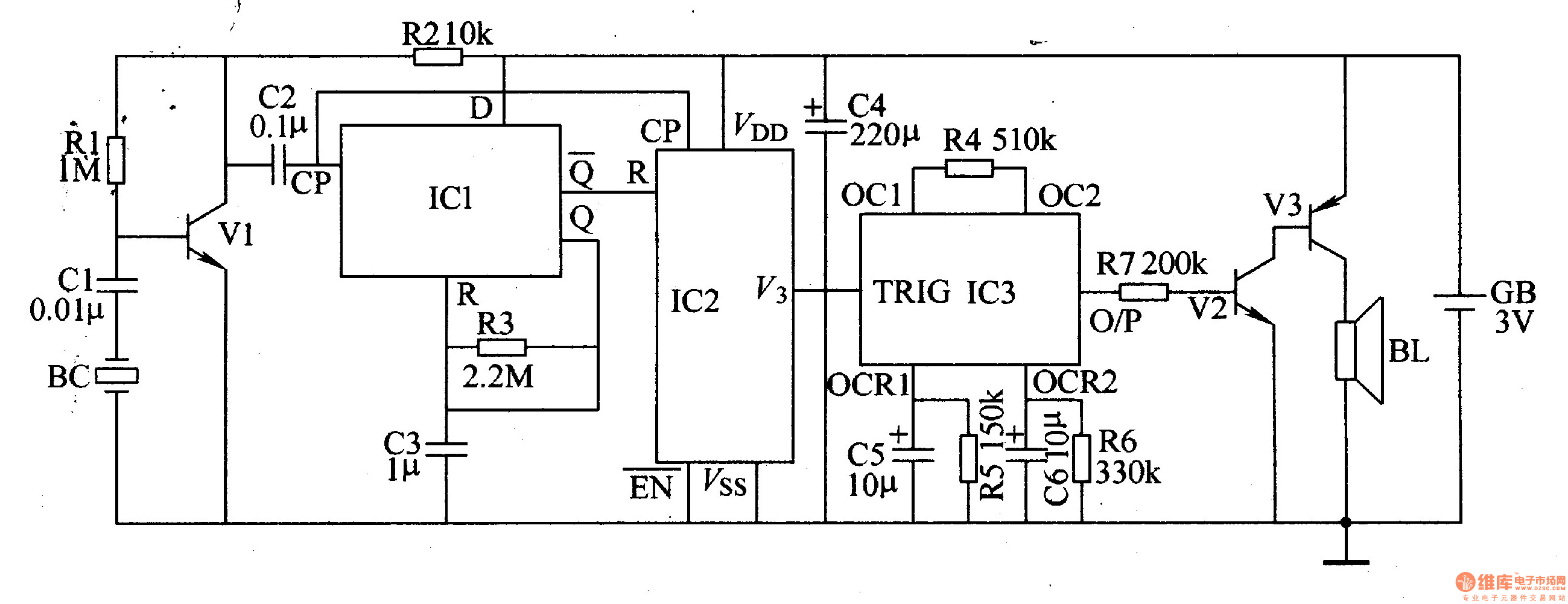
The electronic doorbell circuit consists of a pickup amplifier, a monostable trigger circuit, a pulse counter circuit, a music generating circuit, an audio amplifier circuit, and additional components. The pickup amplifier circuit is composed of a piezoelectric ceramic element, an...
Two-tone electronic doorbell 2
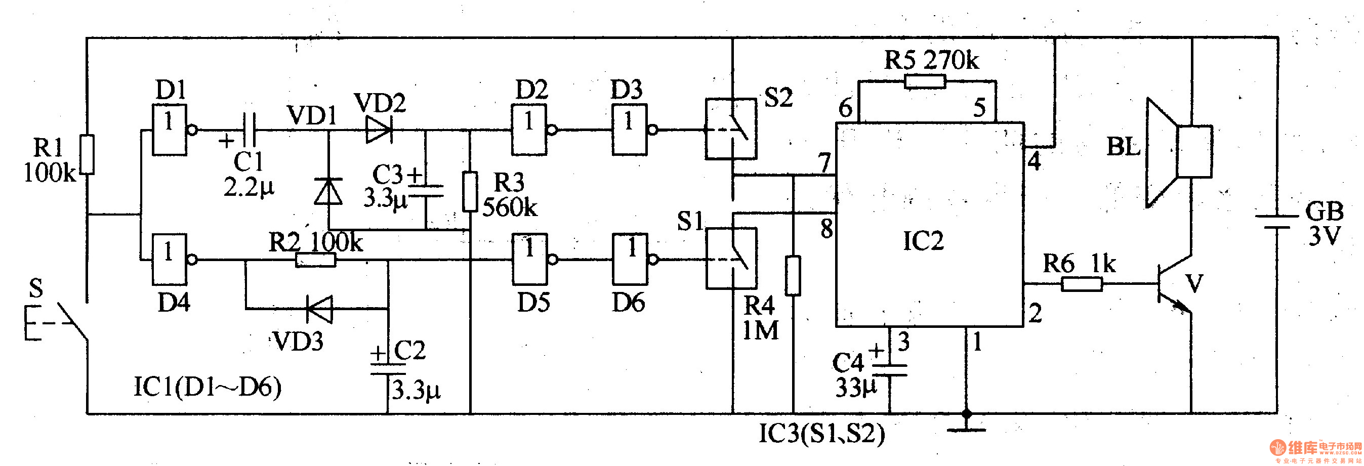
The two-tone electronic doorbell circuit comprises a trigger control circuit and a doorbell generating circuit, as illustrated in Figure 3-108. The trigger control circuit includes a doorbell button (S), resistors (R1-R3), electrical components (C1-C3), diodes (VD1-VD3), six NOT gate integrated...
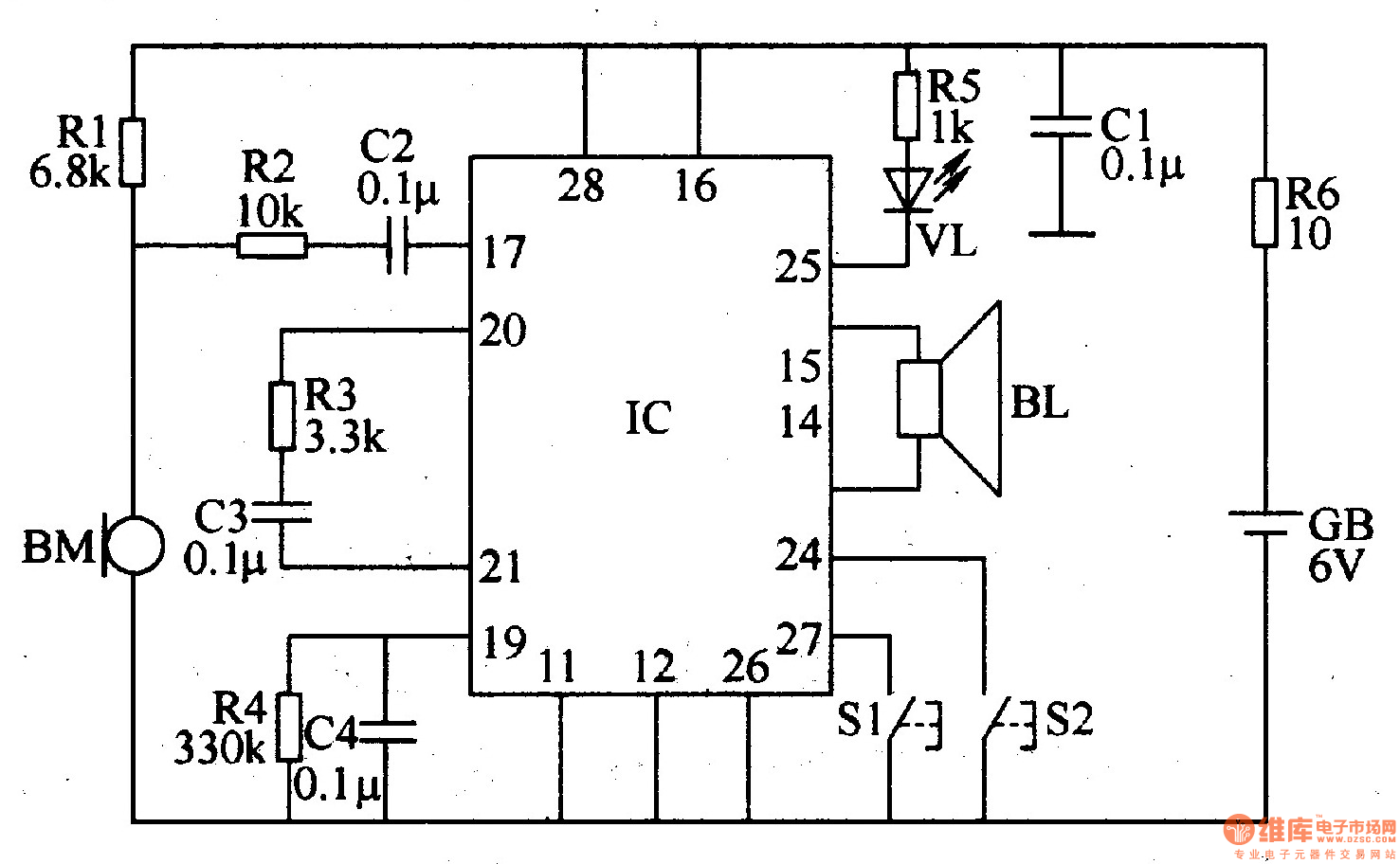
Recordable electronic doorbell
The recordable electronic doorbell consists of a recording and playback integrated circuit (IC), resistors R1-R6, capacitors C1-C4, a microphone (BM), a speaker (BL), control buttons S1 and S2, a battery (GB), and an LED (VL). Resistors R1-R5 should be selected...
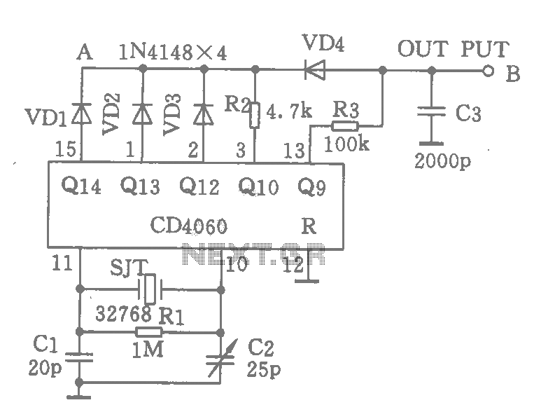
Cheap precision digital clock time base oscillation circuit
A CD4060 integrated circuit, combined with a 32,768 Hz crystal oscillator, is utilized to create a highly accurate clock source that generates 60 pulses per second. The operation is based on the division of the 32,768 Hz pulse output from...
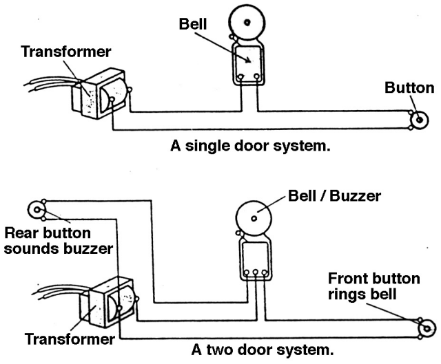
doorbell wiring
Instructions for wiring and installing a doorbell in your home.
The installation of a doorbell involves several key steps to ensure proper functionality and safety. The process typically begins with selecting the appropriate doorbell type, which can be either wired or...
Two-tone electronic doorbell 2
The two-tone electronic doorbell circuit comprises a trigger control circuit and a doorbell generating circuit, as illustrated in Figure 3-108. The trigger control circuit includes a doorbell button (S), resistors (R1-R3), electrical components (C1-C3), diodes (VD1-VD3), six NOT gate integrated...
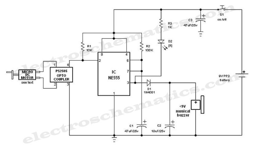
Electronic Doorbell Circuit
This simple and cost-effective ding-dong electronic doorbell circuit is based on IC 8021-2. The IC has an integrated circuitry that generates a ding-dong sound each time its pin 3 is pulled low. The sound is stored in the IC as...
Percussion electronic doorbell 1
The electronic doorbell circuit consists of a pickup amplifier, a monostable trigger circuit, a pulse counter circuit, a music generating circuit, an audio amplifier circuit, and additional components. The pickup amplifier circuit is composed of a piezoelectric ceramic element, an...