


Drum Solenoid Interface for Tap-Tempo Metronome
#piezoelectric
#solenoid
#metronome
#tap-tempo
#drum
#audio interface
#electromagnetic
#music
#rhythm
#percussion
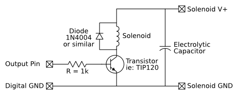
Description: An external piezoelectric element has been added for placement on a bench top, making it more accessible for children. This external piezo element was soldered to the same pads as the built-in piezo element of the Tap-Tempo Metronome. A large piezo element was utilized. For the drum striker, an electromagnetic solenoid was employed, consisting of a coil of wire wound around a movable metal core. When current flows through the coil, the metal core moves a short distance. However, the pins on a microcontroller are relatively weak, providing only 20-40 milliamps (mA) of current, while the solenoid requires a 1 amp draw. Therefore, direct connection of the microcontroller to the solenoid is not feasible due to insufficient current supply. The typical solution to this drive strength issue is to use a transistor as a switch. A common method to drive a large inductive load from a microcontroller is illustrated here. Since the solenoid requires a higher supply voltage, specifically 12V in this instance, an additional power supply must be considered. The circuit employs a transistor capable of handling the solenoid's current (1A). A TIP120 power transistor, functioning as a NPN bipolar junction transistor (BJT), is suitable as it can handle up to 5 amps of current, which is more than adequate for the 1A solenoid. This circuit design is based on an example from the Arduino Playground (PDF). When the microcontroller's output pin is set high, the connection between the transistor's top and bottom terminals allows current to flow through the solenoid. Conversely, when the output pin is low, current ceases to flow, stopping the solenoid's operation. A large electrolytic capacitor is crucial in this circuit, as it assists in supplying the significant current demand of the solenoid, with a capacitance of at least 1000 µF recommended. A resistor is also included to limit the current through the microcontroller pin. An essential component of this circuit is the protection diode, which allows current to flow in one direction. Solenoids, relays, and motors are essentially large coils of wire that produce magnetic fields when current flows through them. When the current is interrupted, the magnetic field attempts to maintain current flow, resulting in a phenomenon known as inductive kickback, which can be harmful to the transistor and microcontroller. Thus, the protection diode is necessary. The firmware should be updated to version 1.15, which provides a startup beep and displays "15" on the screen, generating the necessary pulses on pin 12 for each beat. For those with access to a PIC programmer, the metronome can be updated with the new firmware available on the download page. Plans are underway to enhance the online marketplace to facilitate the sale of updated PIC microcontrollers. The output pin, pin 12, is typically connected to the unused decimal point LEDs in the seven-segment displays. This connection can be easily severed by cutting a trace with a sharp knife, such as an X-Acto knife. Care should be taken to avoid cutting adjacent traces. The cutting process should continue until a visible gap between the two sides is created. A multimeter can be utilized to confirm no continuity between pin 12 on the chip and pin 7 on the seven-segment displays. A wire can then be connected to pin 12 on the chip by forming a small loop at one end of a length of breadboard wire.
The circuit design incorporates a microcontroller interfacing with an electromagnetic solenoid through a TIP120 transistor. The microcontroller controls the solenoid operation by outputting a digital signal to the base of the TIP120, which acts as a switch. The solenoid operates at 12V, necessitating an external power supply that can provide sufficient current. The inclusion of a large electrolytic capacitor ensures that the solenoid receives the necessary current during activation, while the protection diode safeguards the circuit from inductive kickback when the solenoid is deactivated. The resistor serves to limit the current flowing into the microcontroller pin, preventing damage to the microcontroller from excessive current. The firmware update enhances the functionality of the metronome, allowing for improved control and operation. The careful disconnection of pin 12 from the seven-segment display ensures that the microcontroller can effectively manage the solenoid without interference from other components. This comprehensive circuit design illustrates the integration of various electronic components to create a functional and safe metronome system suitable for educational purposes.We added an external piezoelectric element to set on the bench top, making it easier for kids to reach. We simply soldered this external piezo element to the same pads as the Tap-Tempo Metronome`s built-in piezo element.
Here`s the large piezo we used. For the drum striker, we used an electromagnetic solenoid, which consists of a coil of wire wound around a movable metal core. When current is sent through the coil, the metal core moves a short distance. Unfortunately, the pins on a microcontroller are relatively weak, meaning that they can only supply 20-40 milliamps (mA) of current, compared to the 1 amp draw of our solenoid. This means that we can`t directly connect the microcontroller to the solenoid, as not enough current would be supplied.
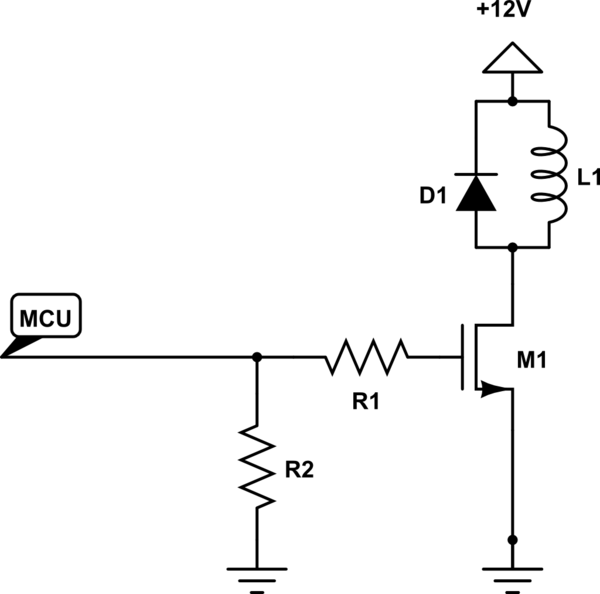
The usual solution to this drive strength problem is to use a transistor as a switch. Here`s a very common way to drive a large inductive load from a microcontroller. Since the solenoid requires a higher supply voltage, 12v in our case, we need to account for the extra power supply. In this circuit, we use a transistor that can easily handle the current through the solenoid (1A). We used a TIP120, which is a kind of power transistor that can be treated like a NPN bipolar junction transistor (BJT) and can handle up to 5 amps of current, more than enough for our 1A solenoid.
While this circuit is very common, the diagram is based on an example diagram from the Arduino Playground (PDF). When the output pin from the microcontroller is driven high, the path between the top and bottom terminals of the transistor are connected, allowing current to flow through the solenoid.
When the output pin is driven low, no current flows through the transistor, stopping the solenoid. The large electrolytic capacitor is very important, as it is used to help supply the large current draw of the solenoid. The capacitance should be at least 1000 uF. The resistor is used to limit current through the pin. One very important part of this circuit is the protection diode. A diode is a special piece of silicon that only conducts electricity in one direction. Solenoids, relays, and motors are essentially just big coils of wire that generate magnetic fields when current is flowing through them.
Sometimes a coil of wire is called an inductor. When the current stops flowing through the coil, the magnetic field tries to keep the current flowing, and actually pushes more current through the wires, a phenomenon called inductive kickback. This current push can be dangerous to the transistor and microcontroller, so we have to add the protection diode.
Update the firmware to version 1. 15. This firmware beeps and displays 15 ³ on startup, and generates the necessary pulses on pin 12 for each beat. If you have access to a PIC programmer, you can update your metronome with the new firmware available from the download page.
We are working to upgrade our online marketplace to allow us to sell updated PIC microcontrollers. Check back soon for more details. The output pin, pin 12, is normally connected to the unused decimal point LEDs in the seven-segment displays. We can easily disconnect it by cutting a trace with a sharp knife, such as an X-Acto knife. Carefully cut the trace by moving the blade over it multiple times. Be careful not to cut the adjacent traces. Keep cutting until you can see the gap between the two sides. If you have a multimeter, you can make sure that there is no continuity between pin 12 on the chip and pin 7 on the seven-segment displays.
Connect a wire to pin 12 on the chip. You can do this easily by taking a length of breadboard wire and forming a tiny loop in one end. Remove the chip from t
The circuit design incorporates a microcontroller interfacing with an electromagnetic solenoid through a TIP120 transistor. The microcontroller controls the solenoid operation by outputting a digital signal to the base of the TIP120, which acts as a switch. The solenoid operates at 12V, necessitating an external power supply that can provide sufficient current. The inclusion of a large electrolytic capacitor ensures that the solenoid receives the necessary current during activation, while the protection diode safeguards the circuit from inductive kickback when the solenoid is deactivated. The resistor serves to limit the current flowing into the microcontroller pin, preventing damage to the microcontroller from excessive current. The firmware update enhances the functionality of the metronome, allowing for improved control and operation. The careful disconnection of pin 12 from the seven-segment display ensures that the microcontroller can effectively manage the solenoid without interference from other components. This comprehensive circuit design illustrates the integration of various electronic components to create a functional and safe metronome system suitable for educational purposes.We added an external piezoelectric element to set on the bench top, making it easier for kids to reach. We simply soldered this external piezo element to the same pads as the Tap-Tempo Metronome`s built-in piezo element.
Here`s the large piezo we used. For the drum striker, we used an electromagnetic solenoid, which consists of a coil of wire wound around a movable metal core. When current is sent through the coil, the metal core moves a short distance. Unfortunately, the pins on a microcontroller are relatively weak, meaning that they can only supply 20-40 milliamps (mA) of current, compared to the 1 amp draw of our solenoid. This means that we can`t directly connect the microcontroller to the solenoid, as not enough current would be supplied.
The usual solution to this drive strength problem is to use a transistor as a switch. Here`s a very common way to drive a large inductive load from a microcontroller. Since the solenoid requires a higher supply voltage, 12v in our case, we need to account for the extra power supply. In this circuit, we use a transistor that can easily handle the current through the solenoid (1A). We used a TIP120, which is a kind of power transistor that can be treated like a NPN bipolar junction transistor (BJT) and can handle up to 5 amps of current, more than enough for our 1A solenoid.
While this circuit is very common, the diagram is based on an example diagram from the Arduino Playground (PDF). When the output pin from the microcontroller is driven high, the path between the top and bottom terminals of the transistor are connected, allowing current to flow through the solenoid.
When the output pin is driven low, no current flows through the transistor, stopping the solenoid. The large electrolytic capacitor is very important, as it is used to help supply the large current draw of the solenoid. The capacitance should be at least 1000 uF. The resistor is used to limit current through the pin. One very important part of this circuit is the protection diode. A diode is a special piece of silicon that only conducts electricity in one direction. Solenoids, relays, and motors are essentially just big coils of wire that generate magnetic fields when current is flowing through them.
Sometimes a coil of wire is called an inductor. When the current stops flowing through the coil, the magnetic field tries to keep the current flowing, and actually pushes more current through the wires, a phenomenon called inductive kickback. This current push can be dangerous to the transistor and microcontroller, so we have to add the protection diode.
Update the firmware to version 1. 15. This firmware beeps and displays 15 ³ on startup, and generates the necessary pulses on pin 12 for each beat. If you have access to a PIC programmer, you can update your metronome with the new firmware available from the download page.
We are working to upgrade our online marketplace to allow us to sell updated PIC microcontrollers. Check back soon for more details. The output pin, pin 12, is normally connected to the unused decimal point LEDs in the seven-segment displays. We can easily disconnect it by cutting a trace with a sharp knife, such as an X-Acto knife. Carefully cut the trace by moving the blade over it multiple times. Be careful not to cut the adjacent traces. Keep cutting until you can see the gap between the two sides. If you have a multimeter, you can make sure that there is no continuity between pin 12 on the chip and pin 7 on the seven-segment displays.
Connect a wire to pin 12 on the chip. You can do this easily by taking a length of breadboard wire and forming a tiny loop in one end. Remove the chip from t

Sight n sound metronome
Precise, adjustable control of beats per minute ranges from a slow tempo of 18 to a rapid tempo of 500. These beats are generated acoustically through a speaker, accompanied by a light that flashes in synchronization. When switch SW1 is...
Metronome with CA741
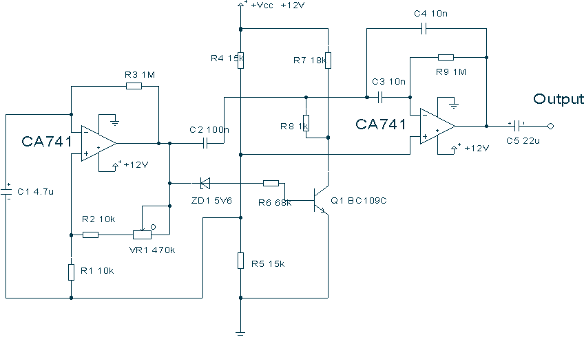
This circuit uses a couple of Op-amps to produce an interesting sound effect. The left hand CA741 is wired as a standard astable and produces the timing pulses, controlled by C1, R2 and VR1. The output is fed via C2...
Piezo Micropositioner Driver Circuit
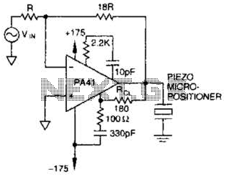
The PA41 from Apex Microtechnology is utilized to drive a piezoelectric micropositioner. The drive voltage is less than 20 V peak-to-peak at the input.
The PA41 is a high-performance power amplifier designed specifically for driving piezoelectric devices, which require precise control...
Power-consumption-limiter
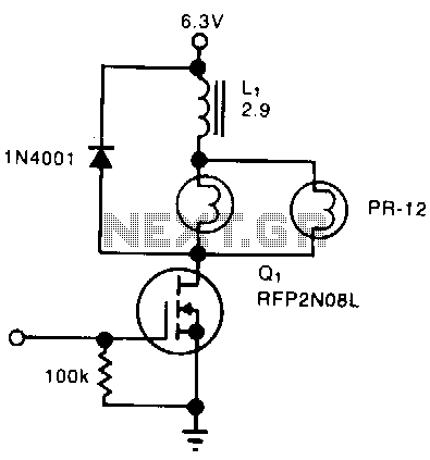
A simple solenoid driver utilizes incandescent lamp filaments as on-indicators to limit power consumption. High magnetic reluctance in the coil of an armature-driven device, such as a solenoid or relay, requires a surge of activation current, followed by a lower...
Final Project
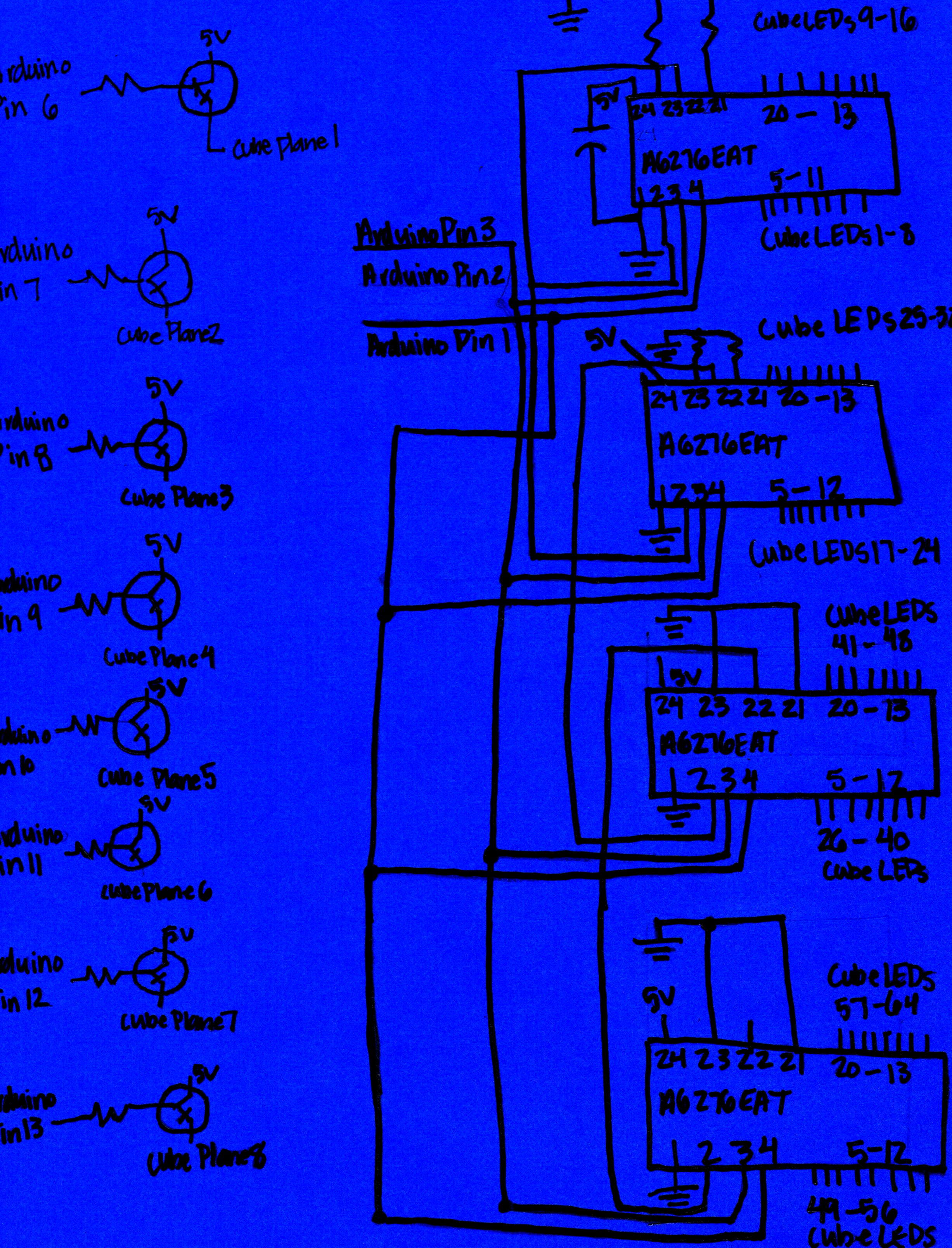
The objective was to create an octave that could be played by pressing a crocodile paddle. This device was designed as an entertainment tool, functioning as a giant piano, allowing users to control sound with their feet. The project was...
Solenoid Driving Circuit
The solenoid requires a specific amount of current to generate its magnetic field. If the solenoid were a perfect inductor, the DC current could rise excessively and potentially damage other circuit components. However, solenoids inherently possess a significant amount of...
Simple Electronic Metronome
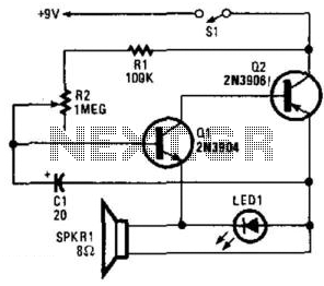
Two complementary transistors create a basic oscillator with a frequency range of approximately 0.5 to several Hz. This circuit serves as a metronome, timer, or pacer for exercise equipment.
The oscillator circuit utilizes a pair of complementary transistors, typically one NPN...
Some Thoughts on Nazi Disc Shaped Flying Machines
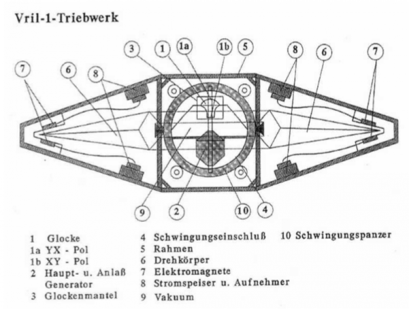
There are two methods to counteract the effects of gravity using electromagnetic forces:
1. The first method involves a rotating magnetic field combined with a radial current flow. The resulting force is directed according to the vector cross product of...

Mini Metronome
Q1 & Q2 provide linear frequency operation of IC1 following P1 resistance variation. Q3 was added in order to obtain a louder click, similar to clockwork metronomes. A 12V micro battery was used to obtain a higher output power and...