


Echo Chamber
#echo effect
#robot voice
#audio processing
#sound modulation
#PCB design
#signal processing
#voice modification
#audio input
#audio output
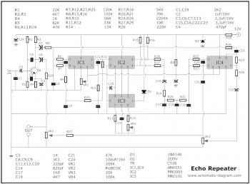
Description: The circuit described is a combination of an echo chamber circuit, which creates a repeated sound effect similar to an echo in a cave, and a robot voice effect circuit that modifies an audio signal to produce a robotic sound. Below is the circuit diagram and PCB layout of an FM wireless microphone. The FM broadcast band operates within a frequency range of 90 MHz (megahertz, or 90 million cycles per second). The FM microphone features a variable tuned circuit that allows it to be adjusted to a quiet frequency within the local FM broadcast band. This mini FM transmitter, designed by Tony van Roon, utilizes two transistors and is straightforward to assemble. Its output can be received on any standard FM radio, with an effective range of approximately 1/4 mile (400 meters) or more, contingent on line-of-sight conditions and potential obstructions. The circuit diagram illustrates a voice transmitter that employs an FM signal carrier to relay voice signals to an FM receiver. The component list includes: R1 = 4.7K, R2 = 330 ohm, C1 = 0.001 uF (1 nF), C2 = 10-40 pF, C3 = 4.7 pF, Q1 = 2N3904, L1 = see text, and miscellaneous components such as an electret microphone. This circuit is optimized for use with dynamic microphones, which are robust and suitable for general applications. Dynamic microphones have a straightforward design with minimal moving parts, making them durable and capable of handling high volume levels from musical instruments or amplifiers. Additionally, a circuit diagram of a voice-operated relay is included, which functions similarly to a sound-activated switch, turning the output switch on and off based on sound input. The relay controls the output of this circuit. The component parts list for this relay circuit includes: R1, R7 = 1K, R2, R4, R8 = 10K.
The echo chamber circuit operates by utilizing feedback loops to create a delayed version of the input audio signal, resulting in an echo effect. This is typically achieved through the use of operational amplifiers configured in a feedback arrangement, where the output is fed back into the input with a controlled delay. The parameters of the circuit, such as delay time and feedback level, can be adjusted to achieve the desired echo effect.
The robot voice effect circuit modifies the input audio signal by altering its frequency and amplitude characteristics. This is often accomplished using a combination of filters and modulation techniques to create a sound that mimics the mechanical quality of a robotic voice. The circuit may include components such as bandpass filters, which allow specific frequency ranges to pass while attenuating others, and modulation circuits that can vary the amplitude of the signal to produce a choppy, robotic sound.
The FM wireless microphone circuit is designed to transmit audio signals over a radio frequency. It employs a simple two-transistor oscillator circuit to generate an FM signal that carries the audio information. The electret microphone converts sound waves into electrical signals, which are then amplified and modulated onto the carrier frequency. The tuning capacitor allows the user to adjust the frequency of the transmitter to avoid interference from other FM signals. The circuit's compact design and ease of assembly make it suitable for various applications, including public speaking and live performances.
The voice-operated relay circuit is designed to respond to sound levels. It typically consists of a microphone that picks up sound, a comparator circuit that processes the audio signal, and a relay that opens or closes a switch based on the detected sound. This type of circuit is useful in applications where automated control is needed based on ambient noise levels, such as in lighting systems or automated door controls. The relay provides a physical switching mechanism that can handle higher power loads, allowing it to control various devices based on the presence of sound.The following circuit is the combination of echo chamber circuit that will make the sound repeated, just like an echo sound when you speak in cave. And the robot voice effect circuit that change the audio signal from input to become sound like a robot voice.
To make the robot voice effect, there are some. Below is the circuit diagram and PCB layo ut of FM wireless microphone: The range of frequencies for the FM broadcast band is 90MHz (MHz = Megahertz or 90 million cycles per second). Because the FM microphone has a variable tuned circuit, it can be tuned to a quiet spot on your local FM broadcast band.
This is a mini FM transmitter built and powered using 2 transistors, designed by Tony van Roon. This small transmitter is simple to build and its transmissions could be picked up on any common FM radio. It possesses a range of approximately 1/4-mile (400 meters) or even more, depending on the line-of-sight, obstructions by big.
The following diagram is the circuit diagram of Voice Transmitter which use FM signal carrier to transmit the vioce signal to the FM receiver device. Components List: R1 = 4. 7K R2 = 330 ohm C1 = 0. 001uF (1nF) C2 = 10-40pF C3 = 4. 7pF Q1 = 2N3904 L1 = see text Misc = Electret mike, . This circuit should be perfect for dynamic microphone. Dynamic microphones are versatile and ideal for general-purpose use. They use a simple design with few moving parts. They are relatively sturdy and resilient to rough handling. They are also better suited to handling high volume levels, such as from certain musical instruments or amplifiers.
They have. This is the circuit diagram of a voice operated relay. It similar with sound activation switch circuit which will turn on and turn off (connect and disconnect) the switch depending on the sound input. The output switch of this circuit is act by a relay. Component Parts list: R1, R7 1K R2, R4, R8 10K.
The echo chamber circuit operates by utilizing feedback loops to create a delayed version of the input audio signal, resulting in an echo effect. This is typically achieved through the use of operational amplifiers configured in a feedback arrangement, where the output is fed back into the input with a controlled delay. The parameters of the circuit, such as delay time and feedback level, can be adjusted to achieve the desired echo effect.
The robot voice effect circuit modifies the input audio signal by altering its frequency and amplitude characteristics. This is often accomplished using a combination of filters and modulation techniques to create a sound that mimics the mechanical quality of a robotic voice. The circuit may include components such as bandpass filters, which allow specific frequency ranges to pass while attenuating others, and modulation circuits that can vary the amplitude of the signal to produce a choppy, robotic sound.
The FM wireless microphone circuit is designed to transmit audio signals over a radio frequency. It employs a simple two-transistor oscillator circuit to generate an FM signal that carries the audio information. The electret microphone converts sound waves into electrical signals, which are then amplified and modulated onto the carrier frequency. The tuning capacitor allows the user to adjust the frequency of the transmitter to avoid interference from other FM signals. The circuit's compact design and ease of assembly make it suitable for various applications, including public speaking and live performances.
The voice-operated relay circuit is designed to respond to sound levels. It typically consists of a microphone that picks up sound, a comparator circuit that processes the audio signal, and a relay that opens or closes a switch based on the detected sound. This type of circuit is useful in applications where automated control is needed based on ambient noise levels, such as in lighting systems or automated door controls. The relay provides a physical switching mechanism that can handle higher power loads, allowing it to control various devices based on the presence of sound.The following circuit is the combination of echo chamber circuit that will make the sound repeated, just like an echo sound when you speak in cave. And the robot voice effect circuit that change the audio signal from input to become sound like a robot voice.
To make the robot voice effect, there are some. Below is the circuit diagram and PCB layo ut of FM wireless microphone: The range of frequencies for the FM broadcast band is 90MHz (MHz = Megahertz or 90 million cycles per second). Because the FM microphone has a variable tuned circuit, it can be tuned to a quiet spot on your local FM broadcast band.
This is a mini FM transmitter built and powered using 2 transistors, designed by Tony van Roon. This small transmitter is simple to build and its transmissions could be picked up on any common FM radio. It possesses a range of approximately 1/4-mile (400 meters) or even more, depending on the line-of-sight, obstructions by big.
The following diagram is the circuit diagram of Voice Transmitter which use FM signal carrier to transmit the vioce signal to the FM receiver device. Components List: R1 = 4. 7K R2 = 330 ohm C1 = 0. 001uF (1nF) C2 = 10-40pF C3 = 4. 7pF Q1 = 2N3904 L1 = see text Misc = Electret mike, . This circuit should be perfect for dynamic microphone. Dynamic microphones are versatile and ideal for general-purpose use. They use a simple design with few moving parts. They are relatively sturdy and resilient to rough handling. They are also better suited to handling high volume levels, such as from certain musical instruments or amplifiers.
They have. This is the circuit diagram of a voice operated relay. It similar with sound activation switch circuit which will turn on and turn off (connect and disconnect) the switch depending on the sound input. The output switch of this circuit is act by a relay. Component Parts list: R1, R7 1K R2, R4, R8 10K.
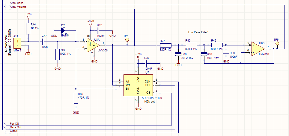
Audio Beat Detect ?« Electronic Product Design
This circuit employs a digital potentiometer to enable the microcontroller to automatically adjust the circuit's gain according to the ambient audio volume. However, a standard potentiometer can be used if automatic adjustment is unnecessary. The low-pass filter design is based...
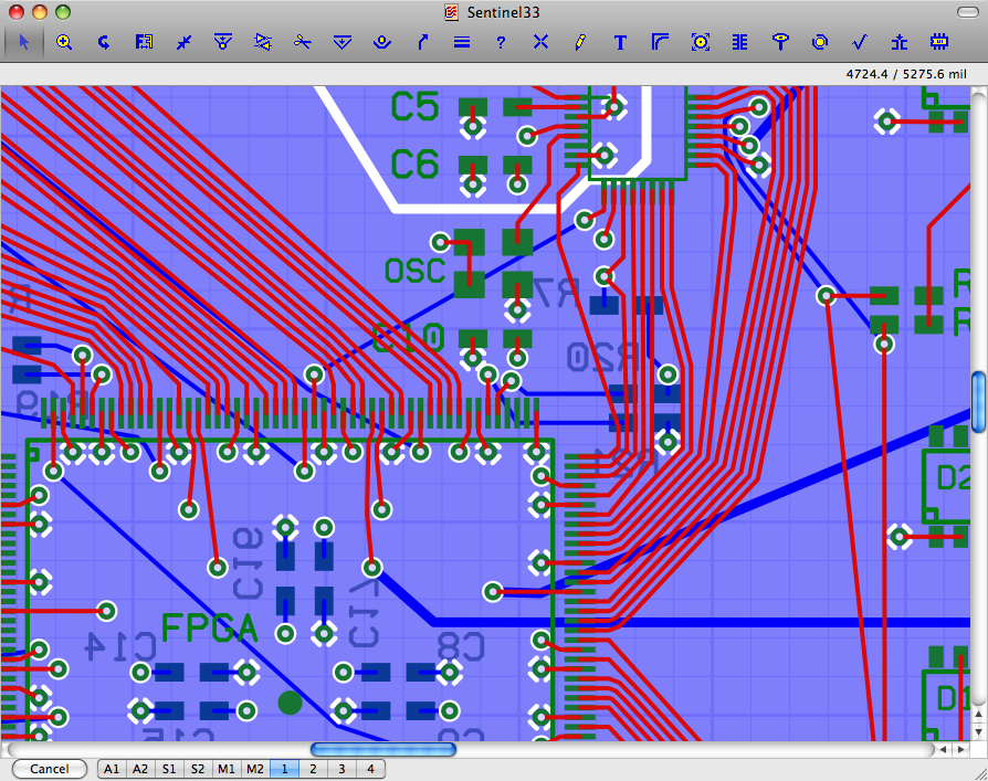
Osmond PCB
Osmond PCB is a flexible tool for designing printed circuit boards. It runs on Macintosh. Its many features include: * Virtually unlimited board sizes * Virtually unlimited number of board layers * Virtually unlimited number of parts.. More: * Spatial...
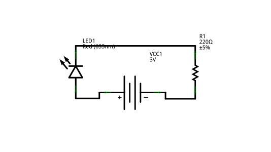
fritzing circuit
Creating circuit boards can be a challenging task. It requires designing a schematic, testing it on a breadboard, laying out the board, and finally printing and etching the board. Fortunately, Fritzing offers a solution. Fritzing is a free, open-source PCB...
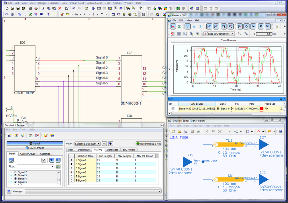
CR-5000 PCB Board Designer
The CR-5000 EDA design suite provides the most advanced PCB design functionality currently available. It is constraints driven, from schematic capture through board layout, to the output of manufacturing data. More: This means that the rules you apply early in...

Sprint-Layout
Design your own Printed Circuit Boards Sprint-Layout is a simple but powerful tool to create layouts for single-sided and double-sided PCBs (Printed Circuit Boards). More: The software comes along with all functions that are necessary for board design. Even professional...
McCAD PCB software
McCAD E.D.S software, a complete family of integrated electronic designs systems for MS Windows and Macintosh OS platforms. McCAD Electronic Design Systems offer a choice of design environments with a wide range of system configurations tailored to the specific needs...
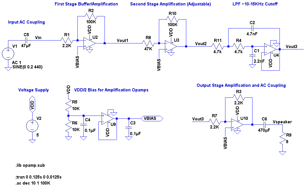
echo effect circuit
A video showcases a friend, James, playing his electric guitar, connected through an audio echo effect system to an amplifier. The echo effect is implemented on a breadboard rather than through hidden pedals or amp options. Apologies are made for...
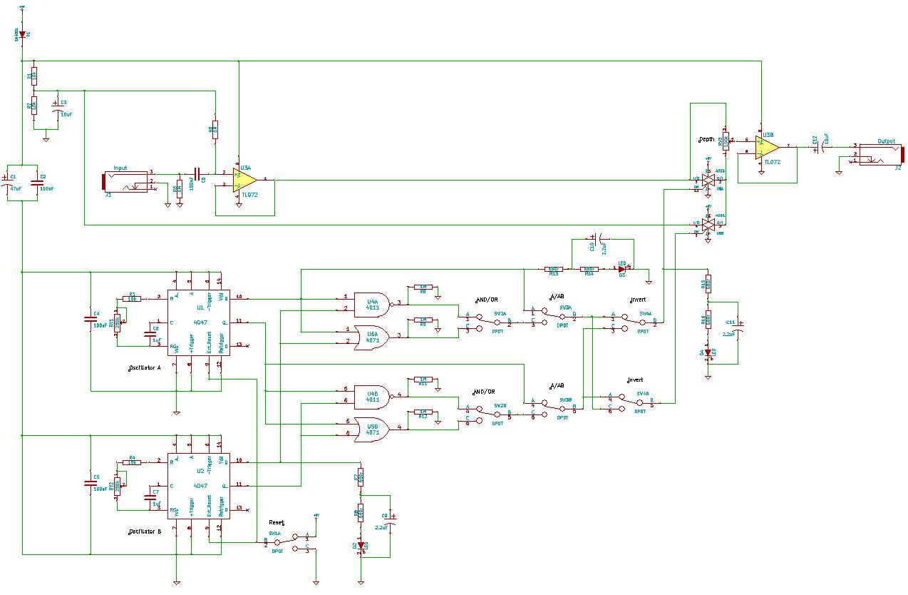
4047/4066 audio slicer
You need to connect pins 1 and 13 of the 4053 to the virtual ground rail (top of C4), not the circuit's 0V rail.
The CD4053 is a triple 2-channel analog multiplexer/demultiplexer integrated circuit, widely used for routing analog signals...

Pulsonix PCB
Innovative yet easy-to-use PCB design editor. Includes many leading edge features for the casual and professional designer alike. Pulsonix contains a complete set of tools for designing Schematics and PCB designs in one integrated interface. Able to import many other...