


Electric Guitar Preamp Mixer and Line Driver
#electric guitar
#preamp
#mixer
#line driver
#pickup
#audio signal
#instrument
#sound processing
#music electronics
#signal conditioning
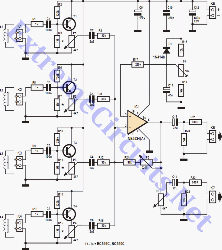
Description: Depending on its design, an electric guitar may have anywhere from one to six pickup elements. Classic acoustic guitars can also benefit from one or more retrofitted pickups. Each pickup produces a specific sound based on the type of sensor and its location on the instrument. When a guitar has multiple pickups, these can be connected together with or without additional components. However, it is preferable for each pickup signal to be buffered individually. These buffered and possibly amplified signals should be level-adjusted to achieve the desired sound. After that, they are mixed and sent to the next stage of the audio processing equipment. Most guitarists agree that pickup elements cannot drive cables longer than about 6 feet without risking significant signal degradation. Guitar pickups typically require a load resistance above 50 kΩ, and sometimes higher than 200 kΩ. Therefore, a preamplifier/buffer is often inserted, whose main function is not high gain but to enable cables between 10 and 30 feet to be connected, representing a capacitance between 90 and 180 pF/m. In the circuit described, each pickup has its own input buffer with a transistor configured as an emitter follower. Each stage has a gain slightly lower than unity, which is acceptable since most pickups provide significant signal levels, typically well over 200 mVpp. The input resistance of the first stage exceeds 200 kΩ, which is appropriate for most inductive pickups available in the market. If higher input resistance is needed, the 1-MΩ resistors marked with asterisks could be omitted, and the 720-kΩ resistors may be increased to 1.2 or 1.5 MΩ, raising the stage's input resistance to around 500 kΩ. To ensure the highest possible undistorted signal can be developed at the output of the first stages, the collector-emitter voltage (VCE) of transistors T1 to T4 should be about half the supply voltage. It is important for the first transistor in the buffer to have low noise and high DC gain. Suitable types include BC549C, BC550C, and the classic BC109C, while BC546C, BC547C, and BC548C may also be considered. The buffered signal from each pickup is adjusted with a potentiometer and sent to the summing circuit of the mixer. The next active element is an audio operational amplifier, type NE5534 or NE5534A (IC1), which provides the necessary signal buffering. The NE5534(A) features low noise, low distortion, and high gain. It can drive a 600Ω line when necessary, but the preferred load is above 2 kΩ. Its amplification is adjustable between 3 and 10 with feedback potentiometer P5. At higher gain values, some limiting and distortion of the output signal occurs, which may be a desirable side effect. The maximum undistorted amplitude of the output signal depends on the supply voltage. If higher gain is needed, the value of P5 may be increased to 470 kΩ. Output K7 includes a volume control potentiometer (P6), which can be omitted if not required. Both outputs K6 and K7 can drive 600Ω loads, including high-impedance headphones. The circuit is straightforward to test and adjust: with no input signal, adjust trimpot P7 for about half the supply voltage at the output of IC1. If precise regulation of the op-amp's output offset is not required, P7 may be omitted, and R17 can be connected to the junction of R18 and R19. The supply voltage ranges from 12 V to 24 V. It is possible to operate the unit off a 9 V power supply, but this lower voltage will limit the output amplitude and gain. The current consumption from a 9 V battery is typically 10 mA, with two 9 V batteries connected in series being the preferred solution. The undistorted output amplitude can reach up to 6 Vpp at a 12 V supply with 2 kΩ loads at the outputs. The unit's frequency response exceeds 20 Hz to 20 kHz, with negligible distortion and noise considering the application.
The described circuit effectively manages the complexities associated with electric guitar signal processing. Each pickup's signal is buffered to maintain integrity and minimize degradation, especially over longer cable runs. The use of an emitter follower configuration for the input buffers ensures that the signal remains strong and clear. The operational amplifier (NE5534/NE5534A) serves as a critical component for further amplification and buffering, allowing for flexibility in gain adjustments while maintaining low distortion levels. The design considerations, such as ensuring the collector-emitter voltage is optimized and selecting suitable transistors for low noise and high gain, contribute to achieving high-quality audio output. The inclusion of adjustable potentiometers for gain and volume allows for user customization, making the circuit adaptable to various performance settings. Overall, this circuit design is robust and well-suited for electric guitar applications, providing reliable performance and sound quality.Depending on its design an electric guitar may have anything from one to six pickup elements. Classic (acoustic) guitars could also benefit from one or more retro- ¬tted pickups. Each pickup has a specific sound depending on the type of sensor and the location on the instrument. When a guitar has more than one pickup these can be connected togeth er with or without additional components. However it is preferable for each pickup signal to be buffered individually. These buffered and possibly amplified signals should be level-adjusted in order to produce the desirable effect (or sound`). After that they are mixed and sent to the next stage of the audio processing equipment. Most guitarists agree that pickup elements cannot drive cables longer than about 6 feet without risking significant signal degradation.
Guitar pickups typically require a load resistance above 50 k © and sometimes higher than 200 k ©, hence a preamplifier/buffer is often inserted, whose main function is not high gain but to enable cables between 10 and 30 feet to be connected representing a capacitance between 90 and 180 pF/m. In the circuit shown here, each pickup has its own input buffer with a transistor con ¬gured as an emitter follower.
Each stage has a gain slightly lower than unity. This is not an issue because most pickups provide significant signal levels, typically well over 200 mVpp. The input resistance of the ¬rst stage exceeds 200 k ©, which is appropriate for most inductive pickups on the market.
If higher input resistance is needed the 1-M © resistors marked with asterisks could be omitted, and the 720-k © ones may be increased to 1. 2 1. 5 M ©. This will raise the stage`s input resistance to around 500 k ©. To ensure the highest possible undistorted signal can be developed at the output of the first stages, the collector-emitter voltage (VCE) of T1 T4 should be about half the supply voltage.
It is important for the first transistor in the buffer to have low noise and high DC gain. The types BC549C and BC550C and the venerable BC109C are perfectly suitable in this respect while the BC546C, BC547C and BC548C may also be considered. The buffered signal from each pickup is adjusted with a potentiometer and sent to the summing circuit of the mixer.
The next active element is an audio operational amplifier type NE5534 or NE5534A (IC1), which provides the required amount of signal buffering. The 5534(A) has low noise, low distortion and high gain. It can drive a 600 © line when necessary, but the preferred load is above 2 k ©. Its amplification is adjustable between 3 and 10 with feedback potentiometer P5. At higher values of the gain some limiting and distortion of the output signal is achieved`, which may well be a desirable side effect.
The maximum undistorted amplitude of the output signal depends on the supply voltage. If higher gain is needed the value of P5 may be increased to 470 k ©. Output K7 has a volume control potentiometer (P6), which could be omitted if not used or required. Both outputs K6 and K7 are capable of driving 600 © loads including high-impedance headphones. The circuit is simple to test and adjust, as follows: with no input signal, adjust trimpot P7 for about half the supply voltage at the output of IC1. If precise regulation of the opamp`s output offset is not required P7 may be omitted and R17 connected to the junction of R18 and R19.
The supply voltage is between 12 V and 24 V. It is possible to run the unit off a 9 V power supply but the lower supply voltage will limit the output amplitude and gain. The current consumption from a 9 V battery is typically 10 mA. Two 9 V batteries connected in series is the preferred solution. The undistorted output amplitude is up to 6 Vpp at a 12 V supply with 2 k © loads at the outputs. The unit`s frequency band exceeds 20 Hz 20 kHz. Distortion and noise were found to be negligible in view of the application.
The described circuit effectively manages the complexities associated with electric guitar signal processing. Each pickup's signal is buffered to maintain integrity and minimize degradation, especially over longer cable runs. The use of an emitter follower configuration for the input buffers ensures that the signal remains strong and clear. The operational amplifier (NE5534/NE5534A) serves as a critical component for further amplification and buffering, allowing for flexibility in gain adjustments while maintaining low distortion levels. The design considerations, such as ensuring the collector-emitter voltage is optimized and selecting suitable transistors for low noise and high gain, contribute to achieving high-quality audio output. The inclusion of adjustable potentiometers for gain and volume allows for user customization, making the circuit adaptable to various performance settings. Overall, this circuit design is robust and well-suited for electric guitar applications, providing reliable performance and sound quality.Depending on its design an electric guitar may have anything from one to six pickup elements. Classic (acoustic) guitars could also benefit from one or more retro- ¬tted pickups. Each pickup has a specific sound depending on the type of sensor and the location on the instrument. When a guitar has more than one pickup these can be connected togeth er with or without additional components. However it is preferable for each pickup signal to be buffered individually. These buffered and possibly amplified signals should be level-adjusted in order to produce the desirable effect (or sound`). After that they are mixed and sent to the next stage of the audio processing equipment. Most guitarists agree that pickup elements cannot drive cables longer than about 6 feet without risking significant signal degradation.
Guitar pickups typically require a load resistance above 50 k © and sometimes higher than 200 k ©, hence a preamplifier/buffer is often inserted, whose main function is not high gain but to enable cables between 10 and 30 feet to be connected representing a capacitance between 90 and 180 pF/m. In the circuit shown here, each pickup has its own input buffer with a transistor con ¬gured as an emitter follower.
Each stage has a gain slightly lower than unity. This is not an issue because most pickups provide significant signal levels, typically well over 200 mVpp. The input resistance of the ¬rst stage exceeds 200 k ©, which is appropriate for most inductive pickups on the market.
If higher input resistance is needed the 1-M © resistors marked with asterisks could be omitted, and the 720-k © ones may be increased to 1. 2 1. 5 M ©. This will raise the stage`s input resistance to around 500 k ©. To ensure the highest possible undistorted signal can be developed at the output of the first stages, the collector-emitter voltage (VCE) of T1 T4 should be about half the supply voltage.
It is important for the first transistor in the buffer to have low noise and high DC gain. The types BC549C and BC550C and the venerable BC109C are perfectly suitable in this respect while the BC546C, BC547C and BC548C may also be considered. The buffered signal from each pickup is adjusted with a potentiometer and sent to the summing circuit of the mixer.
The next active element is an audio operational amplifier type NE5534 or NE5534A (IC1), which provides the required amount of signal buffering. The 5534(A) has low noise, low distortion and high gain. It can drive a 600 © line when necessary, but the preferred load is above 2 k ©. Its amplification is adjustable between 3 and 10 with feedback potentiometer P5. At higher values of the gain some limiting and distortion of the output signal is achieved`, which may well be a desirable side effect.
The maximum undistorted amplitude of the output signal depends on the supply voltage. If higher gain is needed the value of P5 may be increased to 470 k ©. Output K7 has a volume control potentiometer (P6), which could be omitted if not used or required. Both outputs K6 and K7 are capable of driving 600 © loads including high-impedance headphones. The circuit is simple to test and adjust, as follows: with no input signal, adjust trimpot P7 for about half the supply voltage at the output of IC1. If precise regulation of the opamp`s output offset is not required P7 may be omitted and R17 connected to the junction of R18 and R19.
The supply voltage is between 12 V and 24 V. It is possible to run the unit off a 9 V power supply but the lower supply voltage will limit the output amplitude and gain. The current consumption from a 9 V battery is typically 10 mA. Two 9 V batteries connected in series is the preferred solution. The undistorted output amplitude is up to 6 Vpp at a 12 V supply with 2 k © loads at the outputs. The unit`s frequency band exceeds 20 Hz 20 kHz. Distortion and noise were found to be negligible in view of the application.
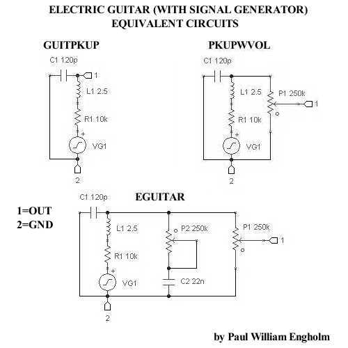
Electric Guitar Pickup SPICE Model (w/Sig. Gen.)
A simple electric guitar SPICE subcircuit has been designed, which features a signal generator producing a 440 Hz sine wave output at 100 mV.
This electric guitar SPICE subcircuit serves as a fundamental tool for simulating the behavior of an electric...
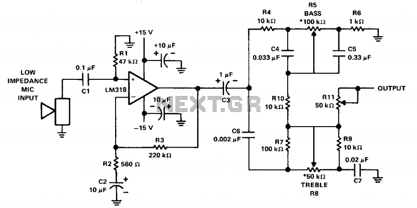
Mike preamp with tone control
The LM318 operational amplifier is configured as a standard non-inverting amplifier. Resistor R1 (47 kΩ) provides a ground path for the bias current of the non-inverting input. The combination of R2 (560Ω) and C2 (10µF) creates a frequency roll-off below...
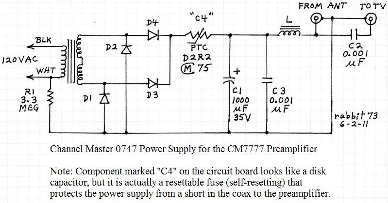
cm7777 preamp
The CM7777 preamp has failed. It is necessary to determine whether the failure is due to the power supply or the preamp itself. The focus is on verifying if the power supply outputs a DC voltage.
To troubleshoot the CM7777 preamp,...
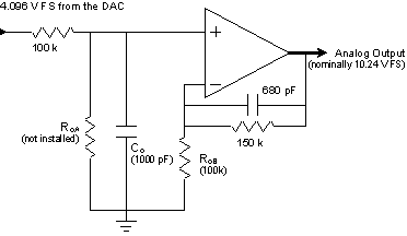
Signal Conditioning Analog Front-end for Microcontrollers
The I/O board incorporates 16-bit resolution voltage analog inputs and outputs, along with a 4-20mA current loop transmitter and receiver for microcontroller applications. The document discusses amplifier circuits and schematics, including a signal conditioning variable gain amplifier, analog filter, and...
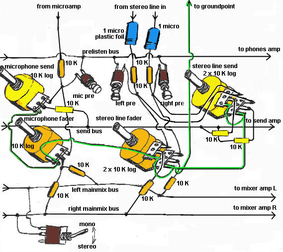
simple mixer
The first two components are passive elements, while the operational amplifier (op-amp) is an active element. The passive elements are two-terminal components, whereas the op-amp is a three-terminal component. A resistor controls the current flowing through it when a voltage...
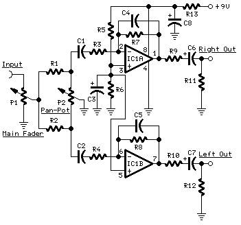
Portable Mixer
A low noise circuit featuring a variable voltage gain (10 - 100) pre-set, primarily designed for high-quality microphone input, but also suitable for low-level line input. The Tone Control Module consists of a three-band (Bass, Middle, Treble) tone control circuit...
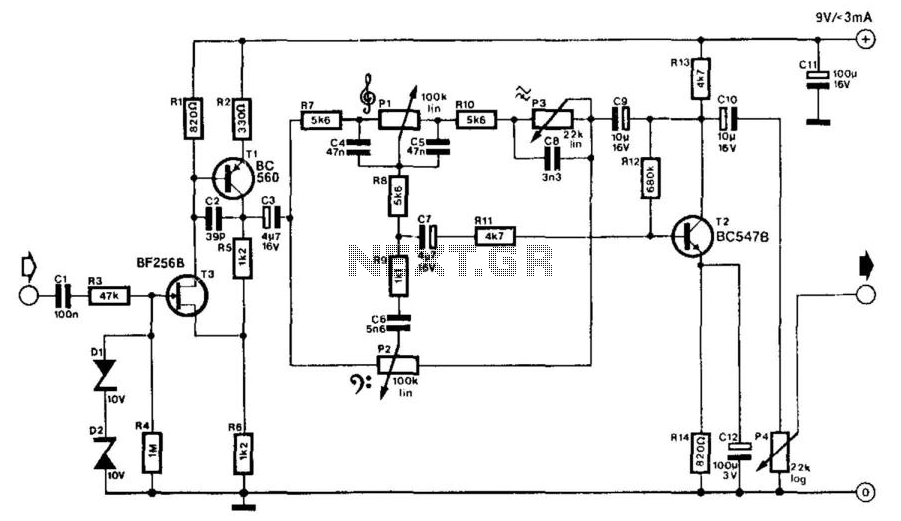
Electric Guitar Matching Amplifier
An electric guitar often needs to be connected to a mixing panel, a tape deck, or a portable studio. While cabling is typically not an issue, the challenge lies in matching the high impedance of the guitar pickup to the...
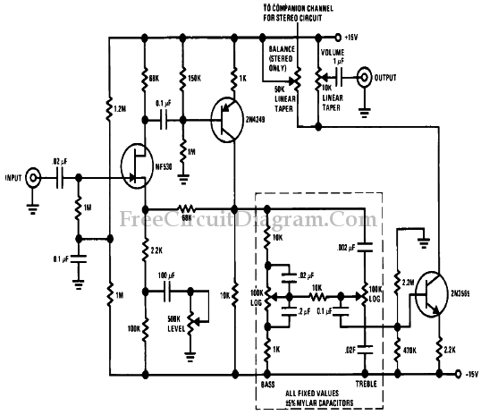
Low Cost High Level Preamp and Tone Control Circuit
To achieve optimal performance as a low noise, high input impedance device, the preamplifier and tone control utilize JFET technology. The circuit is designed to minimize harmonic distortion levels.
The use of Junction Field Effect Transistors (JFETs) in the preamplifier and...
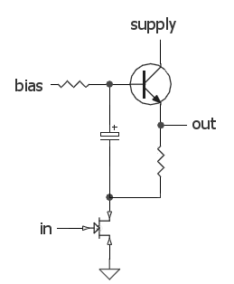
DC biasing audio signal
The audio source will be a line-level audio signal ranging from -2V to +2V AC, which will be passed through a 220µF coupling capacitor followed by a two-pole low-pass filter (RC). The signal will be processed by an Analog-to-Digital Converter...