


Electronic Stethoscope
#stethoscope
#op-amp
#amplifier
#low pass filter
#audio amplification
#medical electronics
#sound detection
#noise reduction
#signal processing
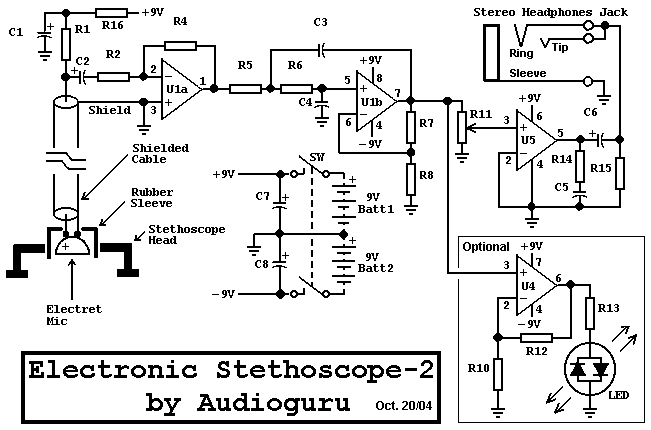
Description: Stethoscopes are not only useful for doctors, but home mechanics, exterminators, spying and any number of other uses. Standard stethoscopes provide no amplification which limits their use. This circuit uses op-amps to greatly amplify a standard stethoscope, and includes a low pass filter to remove background noise.
The described circuit enhances a standard stethoscope's functionality by integrating operational amplifiers (op-amps) to amplify the audio signals captured by the stethoscope. The circuit design typically involves a two-stage amplification process. The first stage consists of a non-inverting op-amp configuration, which provides a gain that can be adjusted based on the resistor values used in the feedback loop. This stage amplifies the weak signals from the stethoscope's diaphragm.
Following the initial amplification, a low-pass filter is implemented to mitigate high-frequency noise that may interfere with the clarity of the sound being monitored. This filter can be realized using a resistor-capacitor (RC) network, where the cutoff frequency is determined by the values of the resistor and capacitor. The cutoff frequency should be set appropriately to allow the relevant audio frequencies (typically in the range of 20 Hz to 20 kHz) to pass while attenuating frequencies above this range that are not of interest.
The final output from the low-pass filter is then routed to a second op-amp stage, which may be configured similarly to the first stage to provide additional gain if necessary. The output can be connected to a speaker or headphones for real-time audio monitoring, or to an analog-to-digital converter (ADC) for further processing in a digital domain, such as recording or analysis.
Power supply considerations for the op-amps must also be addressed, ensuring that the circuit operates within the specified voltage range of the chosen op-amps. Additionally, proper grounding and layout techniques should be employed to minimize noise and ensure stable operation of the circuit.
Overall, this circuit design not only enhances the functionality of a standard stethoscope but also expands its applicability across various fields beyond medicine, including mechanical diagnostics and surveillance.Stethoscopes are not only useful for doctors, but home mechanics, exterminators, spying and any number of other uses. Standard stethoscopes provide no amplification which limits their use. This circuit uses op-amps to greatly amplify a standard stethoscope, and includes a low pass filter to remove background noise.
The described circuit enhances a standard stethoscope's functionality by integrating operational amplifiers (op-amps) to amplify the audio signals captured by the stethoscope. The circuit design typically involves a two-stage amplification process. The first stage consists of a non-inverting op-amp configuration, which provides a gain that can be adjusted based on the resistor values used in the feedback loop. This stage amplifies the weak signals from the stethoscope's diaphragm.
Following the initial amplification, a low-pass filter is implemented to mitigate high-frequency noise that may interfere with the clarity of the sound being monitored. This filter can be realized using a resistor-capacitor (RC) network, where the cutoff frequency is determined by the values of the resistor and capacitor. The cutoff frequency should be set appropriately to allow the relevant audio frequencies (typically in the range of 20 Hz to 20 kHz) to pass while attenuating frequencies above this range that are not of interest.
The final output from the low-pass filter is then routed to a second op-amp stage, which may be configured similarly to the first stage to provide additional gain if necessary. The output can be connected to a speaker or headphones for real-time audio monitoring, or to an analog-to-digital converter (ADC) for further processing in a digital domain, such as recording or analysis.
Power supply considerations for the op-amps must also be addressed, ensuring that the circuit operates within the specified voltage range of the chosen op-amps. Additionally, proper grounding and layout techniques should be employed to minimize noise and ensure stable operation of the circuit.
Overall, this circuit design not only enhances the functionality of a standard stethoscope but also expands its applicability across various fields beyond medicine, including mechanical diagnostics and surveillance.Stethoscopes are not only useful for doctors, but home mechanics, exterminators, spying and any number of other uses. Standard stethoscopes provide no amplification which limits their use. This circuit uses op-amps to greatly amplify a standard stethoscope, and includes a low pass filter to remove background noise.
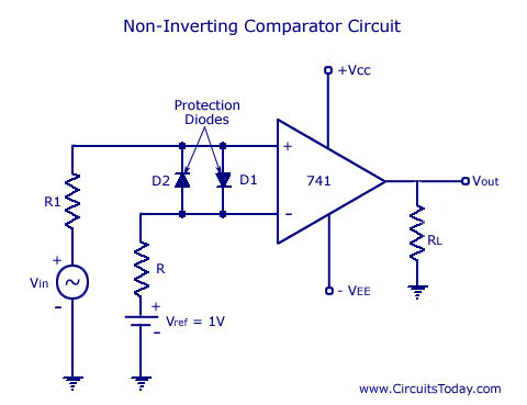
Op-Amp Comparator
A working schematic diagram and design of the uA741 integrated circuit (IC) operational amplifier comparator circuit is provided, including the waveforms for both inverting and non-inverting comparators.
The uA741 operational amplifier is a versatile component widely used in various applications, including...
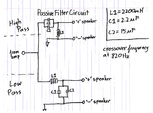
iPod/MP3 Mini Speaker System
Listen and share music wherever you go with the mini speaker system project. This project allows for music playback in various locations such as dorms, cubicles, or the beach. It serves as an excellent introduction to circuit systems, featuring an...
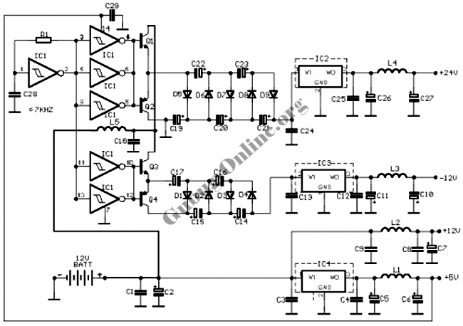
DC-Coupled Audio Amplifier Circuit
This design circuit for audio amplifiers with DC coupling to the load is not commonly used today, despite its clear advantages. One advantage is the elimination of the need for a second (symmetric) power supply, and another is the improved...
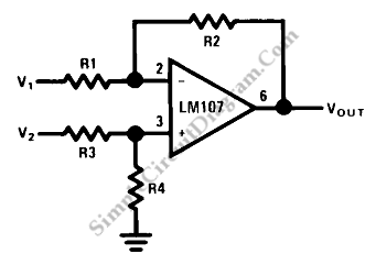
Op-Amp Circuit: Difference Amplifier
This circuit is a difference amplifier. It functions as an inverting amplifier that enables the subtraction of two voltages, effectively performing a summation.
The difference amplifier is a fundamental circuit configuration in analog electronics, primarily used for amplifying the difference between...
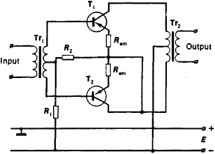
Amplifier circuit
An amplifier is a device that accepts a varying input signal and produces an output signal that varies in the same way as the input but has a larger amplitude. The input signal may be a current, voltage, mechanical motion,...

LOW PASS WITH 10 kHz CUTOFF
The next throttle is a prototype assembled for testing purposes. It represents a modification of the basic transistor throttle. The SPDT switch enables the throttle to deliver either full or half-wave DC output. The value of the 8 µF capacitors...
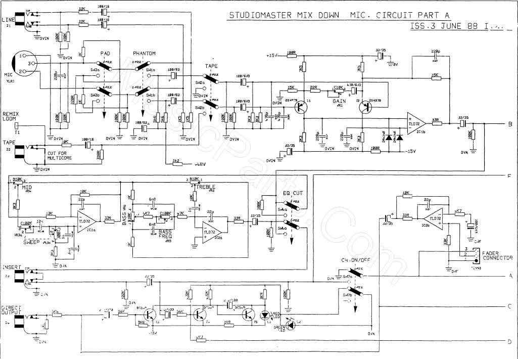
standard operational amplifier op amp circuits
This scan is from an old ETI Circuits #2 publication from the 1970s. It contains valuable operational amplifier information that is highly useful. With some knowledge, the six circuits presented serve as an instant reference, enabling various applications. These circuits...
High Impedance DC Voltmeter Circuit Using Op Amp
This design outlines a high impedance DC voltmeter circuit utilizing the uA741 integrated circuit (IC). The uA741 is configured as a non-inverting DC amplifier. The circuit incorporates negative feedback through a DC meter that requires 1 mA for full-scale deflection....
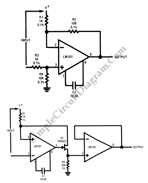
Op-Amp Application: Level Shifting Amplifier
In linear equipment design, it is sometimes necessary to take a voltage that is referenced to a certain DC level and generate an amplified output that is also referenced.
In linear circuit design, the process of amplifying a voltage that is...