


FDM stereo decoder
#stereo decoder
#FDM
#PC-filter
#capacitor
#switching level
#LED circuit
#audio processing
#stereo indicator
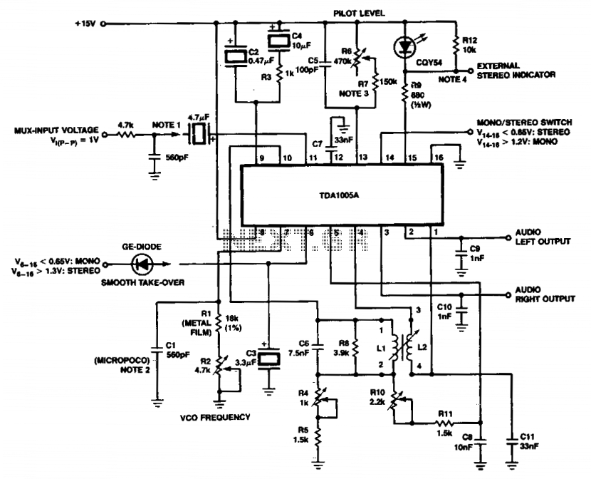
Description: For other input structures, refer to Figures 6 to 11, which illustrate various configurations. The micropoco capacitor has a temperature coefficient of 125.10^-6 i 60.10^k^-1. In simplified circuits, a fixed resistor (e.g., 620kΩ) can be employed to ensure a guaranteed switching level of less than 16mV. Either the LEO circuit or an external stereo indicator can be utilized.
Coil data: Inductance (L) is 2.6 mH, quality factor (Qi) is -35, and minimum quality factor (Qmin) is 30. The coil has 357 turns, with dimensions E3.4 and N3 4, constructed using a wire diameter of 0.09 mm, achieving a 100% fill factor.
The circuit described incorporates various components essential for its operation. The micropoco capacitor, characterized by its temperature coefficient, plays a crucial role in stabilizing the circuit's performance across varying thermal conditions. The specified temperature coefficient indicates the capacitor's sensitivity to temperature changes, which is critical in precision applications.
The use of a fixed resistor, such as the 620kΩ resistor, ensures that the circuit maintains a consistent switching threshold, which is particularly important for digital circuits where signal integrity is paramount. The guaranteed switching level of less than 16mV allows for reliable operation in low-voltage scenarios, minimizing the risk of false triggering due to noise.
The coil data provided indicates an inductive component with specific characteristics that contribute to the overall circuit functionality. The inductance value of 2.6 mH suggests that the coil can store a significant amount of energy in its magnetic field, which is beneficial in applications such as filtering or signal conditioning. The quality factor (Qi) of -35 and minimum quality factor (Qmin) of 30 provide insight into the coil's efficiency and performance, with higher quality factors indicating better performance in resonant applications.
The construction details of the coil, including the number of turns (357) and the wire diameter (0.09 mm), suggest careful design considerations to optimize the coil's performance. The mention of a scrambled winding technique may imply that the coil is designed to reduce parasitic capacitance and improve overall efficiency, which is essential in high-frequency applications.
In conclusion, the circuit's design integrates a micropoco capacitor, a fixed resistor for switching stability, and a well-defined coil, all of which contribute to its robustness and reliability in various electronic applications. The ability to utilize either the LEO circuit or an external stereo indicator provides flexibility in implementation, catering to different user requirements or preferences. For other input structures see Figures 6 to 11; shown here with PC-filter (Figure ß). The micropoco capacitor has a temperature coefficient of 125.10"6i 60.10" k"1. In simplified circuits a fixed resistor (e.g. 620k) can be used for a guaranteed switching level Of < 16mV. Either the LEO circuit or an external stereo indicator can be used. Coil data: L, l-2.6mh qi.-35; qmin-30 - 357W turns; E3.4 N3 4 « £97 ft turns: scrambled wound with wire diameter 0.09mm, - 100% =» T2%.
Coil data: Inductance (L) is 2.6 mH, quality factor (Qi) is -35, and minimum quality factor (Qmin) is 30. The coil has 357 turns, with dimensions E3.4 and N3 4, constructed using a wire diameter of 0.09 mm, achieving a 100% fill factor.
The circuit described incorporates various components essential for its operation. The micropoco capacitor, characterized by its temperature coefficient, plays a crucial role in stabilizing the circuit's performance across varying thermal conditions. The specified temperature coefficient indicates the capacitor's sensitivity to temperature changes, which is critical in precision applications.
The use of a fixed resistor, such as the 620kΩ resistor, ensures that the circuit maintains a consistent switching threshold, which is particularly important for digital circuits where signal integrity is paramount. The guaranteed switching level of less than 16mV allows for reliable operation in low-voltage scenarios, minimizing the risk of false triggering due to noise.
The coil data provided indicates an inductive component with specific characteristics that contribute to the overall circuit functionality. The inductance value of 2.6 mH suggests that the coil can store a significant amount of energy in its magnetic field, which is beneficial in applications such as filtering or signal conditioning. The quality factor (Qi) of -35 and minimum quality factor (Qmin) of 30 provide insight into the coil's efficiency and performance, with higher quality factors indicating better performance in resonant applications.
The construction details of the coil, including the number of turns (357) and the wire diameter (0.09 mm), suggest careful design considerations to optimize the coil's performance. The mention of a scrambled winding technique may imply that the coil is designed to reduce parasitic capacitance and improve overall efficiency, which is essential in high-frequency applications.
In conclusion, the circuit's design integrates a micropoco capacitor, a fixed resistor for switching stability, and a well-defined coil, all of which contribute to its robustness and reliability in various electronic applications. The ability to utilize either the LEO circuit or an external stereo indicator provides flexibility in implementation, catering to different user requirements or preferences. For other input structures see Figures 6 to 11; shown here with PC-filter (Figure ß). The micropoco capacitor has a temperature coefficient of 125.10"6i 60.10" k"1. In simplified circuits a fixed resistor (e.g. 620k) can be used for a guaranteed switching level Of < 16mV. Either the LEO circuit or an external stereo indicator can be used. Coil data: L, l-2.6mh qi.-35; qmin-30 - 357W turns; E3.4 N3 4 « £97 ft turns: scrambled wound with wire diameter 0.09mm, - 100% =» T2%.
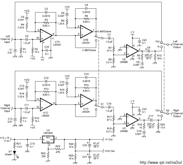
ARRL Handbook Audio Intelligibility Enhancer
Assistance is sought for building the N4GG audio intelligibility enhancer project as detailed in the ARRL Handbook. A circuit board has been ordered from Far Circuits, but there are difficulties in sourcing the necessary components. Attempts have been made to...
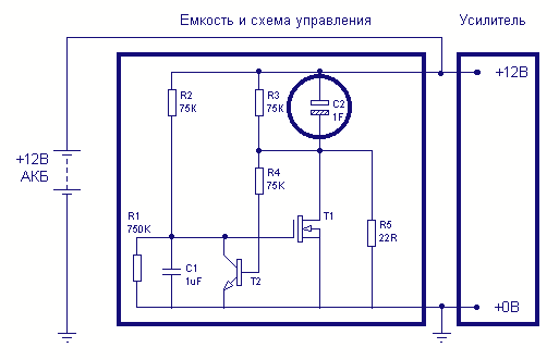
Car Large capacitor charge controllers
One-farad capacitors require some care. It's common knowledge that they must be pre-charged with a current-limiting resistor before plugging in. It is less common knowledge that those fifty-dollar smart cap controllers are in fact very simple devices, two dollars for...
own capacitor
The capacitor is composed of two sheets of aluminum foil. It is essential to keep the foil within the plastic packets and connect them using crocodile clips, ensuring that the clips do not touch each other. The initial frequency of...
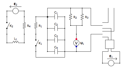
Capacitor Box Circuit
This is the discharging circuit. The red lines indicate the flow of energy from the capacitors to the terminals when the switch is in the upward position. The circuit is complete due to the connection of the terminals by Ni-Chrome...
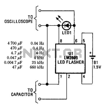
Simple Capacitor Tester
An LM3909 LED flasher functions as an oscillator, with the frequency determined by the capacitor connected to its terminals. The LED can be utilized to visually count frequency using a stopwatch for large capacitors (C > 500µF).
The LM3909 is an...
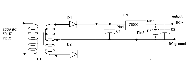
Power supply circuit design
C1 is a 1000 microfarad aluminum electrolytic capacitor. For loads less than 100mA, a 220 microfarad capacitor can be substituted. The voltage rating should be 2.5 times the output voltage.
C1 serves as a critical component in various electronic circuits, particularly...
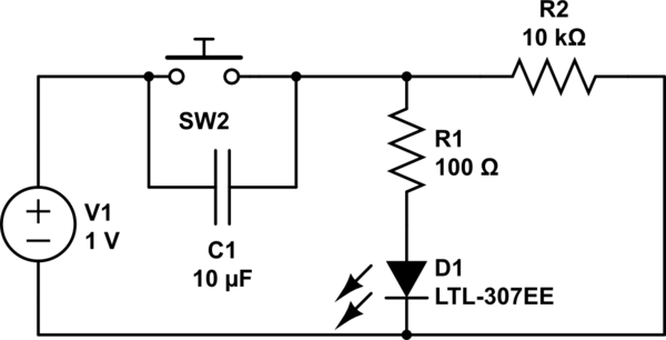
How the capacitor works (in a debouncing circuit)
Understand why the LED does not light up, as the capacitor appears to be bypassing the switch. When the capacitor is fully charged, it does not conduct electricity. Although the individual is a beginner, after 20 hours of studying various...
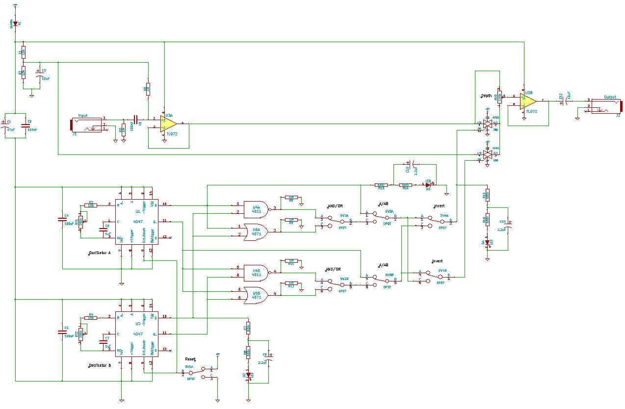
4047/4066 audio slicer
You need to connect pins 1 and 13 of the 4053 to the virtual ground rail (top of C4), not the circuit's 0V rail.
The CD4053 is a triple 2-channel analog multiplexer/demultiplexer integrated circuit, widely used for routing analog signals...
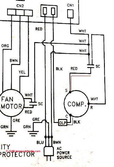
Starting Capacitors
Instructions for electric motor start-run capacitors include the use of starting capacitors for air conditioner compressor motors and other electric motors like pumps. This involves diagnostic checks for start or run capacitors, including how to use a volt-ohm meter (VOM)...