


Fuzz box 1
#fuzz box
#distortion
#transistor amplifier
#signal clipping
#audio effect
#diodes
#filter
#high frequency noise
#guitar effect
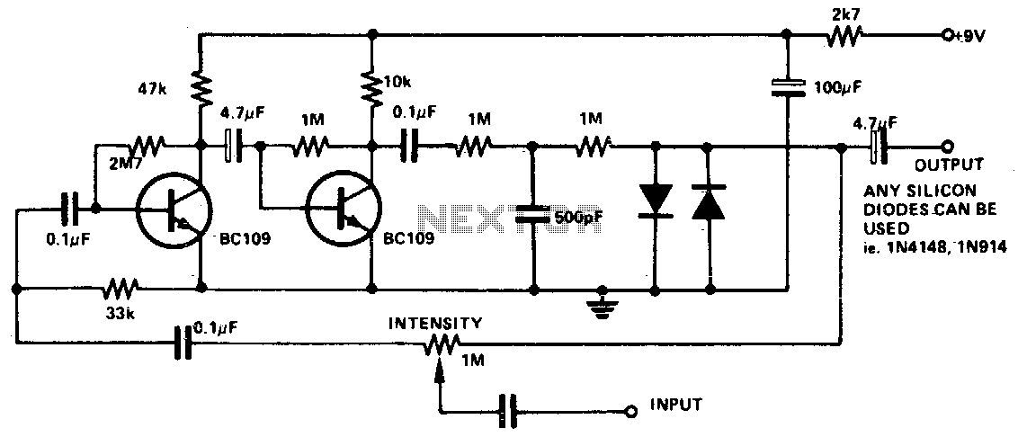
Description: The input signal is amplified by the transistors. The distorted output is then clipped by the two diodes, and the high-frequency noise is filtered from the circuit via the 500 pF capacitor. The 1 M potentiometer adjusts the intensity of the fuzz from maximum to no fuzz (normal playing).
The circuit described functions primarily as a fuzz effect pedal, commonly used in electric guitar applications. The initial stage of the circuit involves a transistor amplifier configuration, where the input audio signal is fed into one or more transistors. These transistors are configured to amplify the input signal, which introduces distortion due to the non-linear characteristics of the transistors when driven beyond their linear operating range.
Following amplification, the distorted output signal is subjected to clipping through two diodes. This clipping process is essential in shaping the fuzz effect, as it limits the voltage peaks of the signal, creating the characteristic sound associated with fuzz pedals. The choice of diodes can significantly influence the tonal quality of the output; silicon diodes typically yield a sharper clipping, while germanium diodes produce a smoother, warmer distortion.
To ensure that the output signal remains clean from unwanted high-frequency noise, a 500 pF capacitor is employed. This capacitor acts as a low-pass filter, effectively shunting high-frequency components to ground while allowing the desired audio frequencies to pass through. The placement of this capacitor is crucial, as it helps maintain the integrity of the fuzz sound by preventing harsh noise artifacts from interfering with the output.
Additionally, the inclusion of a 1 MΩ potentiometer allows for user control over the fuzz intensity. This potentiometer adjusts the gain of the circuit, providing a range from maximum fuzziness—characterized by a heavily distorted sound—to a clean tone, which is ideal for normal playing situations. By turning the potentiometer, the player can seamlessly transition between different sonic textures, making the circuit versatile for various musical styles.
Overall, this circuit design effectively combines amplification, distortion, clipping, filtering, and user control to create a dynamic and expressive fuzz effect suitable for electric guitar applications.The input signal is amplified by the transistors. The distorted output is then clipped by the two diodes and the high frequency noise is filtered from the circuit via the 500 pF capacitor The 1 M pot adjusts the intensity of the fuzz from maximum to no fuzz (normal playing).
The circuit described functions primarily as a fuzz effect pedal, commonly used in electric guitar applications. The initial stage of the circuit involves a transistor amplifier configuration, where the input audio signal is fed into one or more transistors. These transistors are configured to amplify the input signal, which introduces distortion due to the non-linear characteristics of the transistors when driven beyond their linear operating range.
Following amplification, the distorted output signal is subjected to clipping through two diodes. This clipping process is essential in shaping the fuzz effect, as it limits the voltage peaks of the signal, creating the characteristic sound associated with fuzz pedals. The choice of diodes can significantly influence the tonal quality of the output; silicon diodes typically yield a sharper clipping, while germanium diodes produce a smoother, warmer distortion.
To ensure that the output signal remains clean from unwanted high-frequency noise, a 500 pF capacitor is employed. This capacitor acts as a low-pass filter, effectively shunting high-frequency components to ground while allowing the desired audio frequencies to pass through. The placement of this capacitor is crucial, as it helps maintain the integrity of the fuzz sound by preventing harsh noise artifacts from interfering with the output.
Additionally, the inclusion of a 1 MΩ potentiometer allows for user control over the fuzz intensity. This potentiometer adjusts the gain of the circuit, providing a range from maximum fuzziness—characterized by a heavily distorted sound—to a clean tone, which is ideal for normal playing situations. By turning the potentiometer, the player can seamlessly transition between different sonic textures, making the circuit versatile for various musical styles.
Overall, this circuit design effectively combines amplification, distortion, clipping, filtering, and user control to create a dynamic and expressive fuzz effect suitable for electric guitar applications.The input signal is amplified by the transistors. The distorted output is then clipped by the two diodes and the high frequency noise is filtered from the circuit via the 500 pF capacitor The 1 M pot adjusts the intensity of the fuzz from maximum to no fuzz (normal playing).
Rejection filter
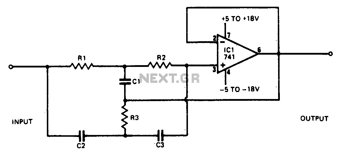
This narrowband filter utilizing the 741 operational amplifier can achieve a rejection level of up to 60 dB. By employing resistors with a value of 100 K ohms and capacitors of 320 pF, the circuit effectively rejects frequencies at 50...
EasyVibe guitar effect
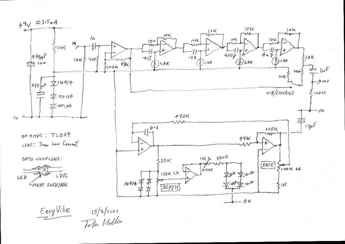
I aimed to copy the sound rather than the vintage circuit. Easy to build, low current consumption, no signal level changes on bypass, quiet and, most importantly, it does that Bridge of Sighs thing.
The circuit described focuses on replicating the...
af filter
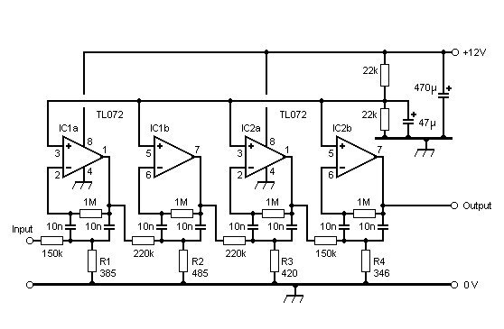
The graphs below illustrate the computer predictions of filter performance provided by Harry PA0LQ. Click on the thumbnail to view the full-size graph. A significant challenge in aligning the filter was the lack of access to a frequency counter with...
Ultra-Flanger guitar effect
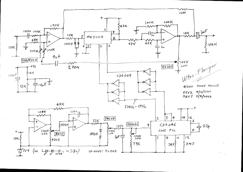
I was originally going to develop a minimum part count version of the EH Electric Mistress. Instead I went for a something with the versatility of an MXR flanger and the extra wide sweep that the A/DA flanger was known...
Electronic filter
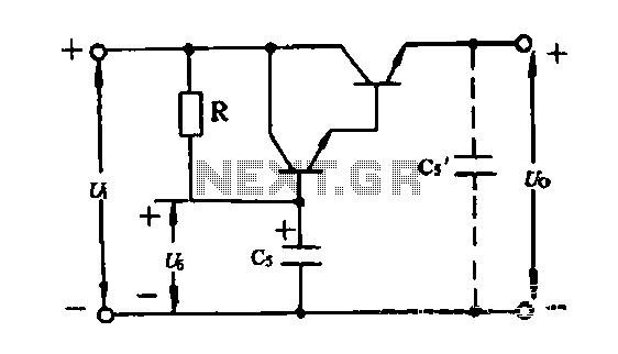
An electronic filter is utilized to enhance the filtering effect of capacitor C5. Capacitors in this configuration form a composite circuit with the electronic filter, as illustrated in the accompanying figure. The advantage of using smaller capacitors (5 to 20...
Antialiasing And Sync-Compensation Filter
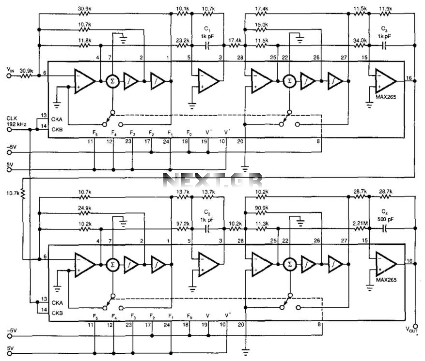
Two dual-biquad filter chips and some external components form a multipurpose filter to reconstruct D/A converter signals. Connected to a converter's output, the filter provides antialiasing, reduces the D/A converter's quantization noise, and compensates for the "sync" function (attenuation). The...
ROTARY SWITCH DEBOUNCE
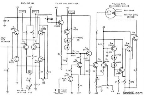
A three-stage active Butterworth bandpass input filter is utilized in a radioteletype demodulator to differentiate RTTY tones from one another and from noise. The filter is centered at 2200 Hz and has a bandwidth of approximately 260 Hz, allowing for...
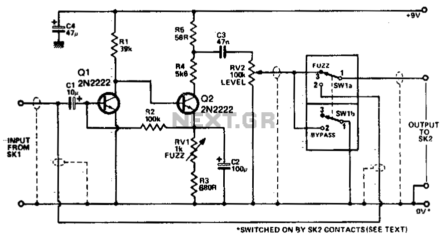
Fuzz box 5
Transistors Q1 and Q2 amplify the incoming signal, and the gain is such that the input will overload when used with an electric guitar. RV1 adjusts the amount of feedback present, and hence voltage gain. The output is, therefore, a...
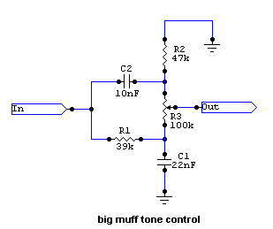
Cook Your Own Distortion
In the late 1960s, the first distortion effect boxes were developed to replicate the sound of razored cones and overdriven amplifiers. Today, most amplifiers feature a distortion control, yet distortion effects remain popular. This discussion will focus on the methods...