


Fuzz box 2
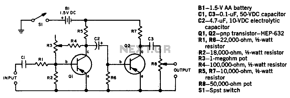
Description: Potentiometer R3 adjusts the degree of fuzz, while R8 controls the output level. Due to the inability of R3 to completely eliminate the fuzz effect, a bypass switch is necessary to connect the input directly to the output terminals for a fuzz-free sound.
In this circuit, the potentiometer R3 serves as a variable resistor that allows the user to modify the amount of fuzz applied to the audio signal. By rotating R3, the resistance changes, altering the feedback and gain characteristics of the fuzz circuit, which ultimately affects the tonal quality and intensity of the fuzz effect. The second potentiometer, R8, functions as a level control that adjusts the overall output amplitude of the signal coming from the fuzz circuit. This allows the user to balance the fuzz effect with the desired output level, ensuring that the sound remains within a usable range.
To achieve a fuzz-free sound, a bypass switch is integrated into the circuit design. This switch, when engaged, creates a direct path for the audio signal from the input to the output, bypassing the fuzz circuit entirely. This feature is essential for musicians and audio engineers who require a clean sound without any distortion or fuzz artifacts. The bypass switch typically consists of a single-pole double-throw (SPDT) configuration, which allows for seamless switching between the fuzz effect and the clean signal.
In summary, the combination of R3 and R8 allows for versatile sound shaping capabilities, while the inclusion of a bypass switch ensures that users can easily toggle between fuzzed and clean audio outputs, catering to a wide range of musical styles and preferences. The careful selection of component values and configurations will affect the overall performance of the circuit, making it crucial to consider the desired application when designing and implementing this schematic.Potentiometer R3 sets the degree of fuzz, and R8 sets the output level Since the fuzz effect cannot be completely eliminated by R3, fuzz-free sound requires a bypass switch from the input to output terminals.
In this circuit, the potentiometer R3 serves as a variable resistor that allows the user to modify the amount of fuzz applied to the audio signal. By rotating R3, the resistance changes, altering the feedback and gain characteristics of the fuzz circuit, which ultimately affects the tonal quality and intensity of the fuzz effect. The second potentiometer, R8, functions as a level control that adjusts the overall output amplitude of the signal coming from the fuzz circuit. This allows the user to balance the fuzz effect with the desired output level, ensuring that the sound remains within a usable range.
To achieve a fuzz-free sound, a bypass switch is integrated into the circuit design. This switch, when engaged, creates a direct path for the audio signal from the input to the output, bypassing the fuzz circuit entirely. This feature is essential for musicians and audio engineers who require a clean sound without any distortion or fuzz artifacts. The bypass switch typically consists of a single-pole double-throw (SPDT) configuration, which allows for seamless switching between the fuzz effect and the clean signal.
In summary, the combination of R3 and R8 allows for versatile sound shaping capabilities, while the inclusion of a bypass switch ensures that users can easily toggle between fuzzed and clean audio outputs, catering to a wide range of musical styles and preferences. The careful selection of component values and configurations will affect the overall performance of the circuit, making it crucial to consider the desired application when designing and implementing this schematic.Potentiometer R3 sets the degree of fuzz, and R8 sets the output level Since the fuzz effect cannot be completely eliminated by R3, fuzz-free sound requires a bypass switch from the input to output terminals.
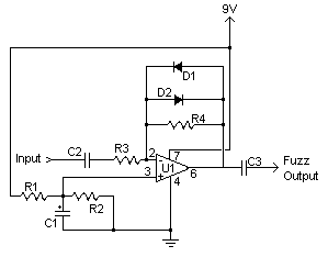
Fuzz Guitar Effect circuit
Fuzz is one of the classic guitar effects, and this simple circuit generates it quite well. The circuit is so compact that it can be built into guitars or amps that do not have built-in fuzz to add that capability...
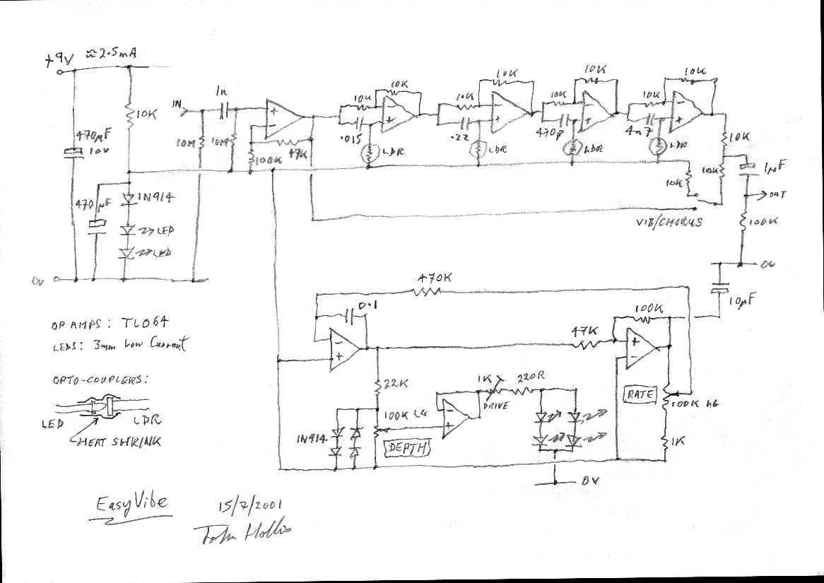
EasyVibe guitar effect
I aimed to copy the sound rather than the vintage circuit. Easy to build, low current consumption, no signal level changes on bypass, quiet and, most importantly, it does that Bridge of Sighs thing.
The circuit described focuses on replicating the...
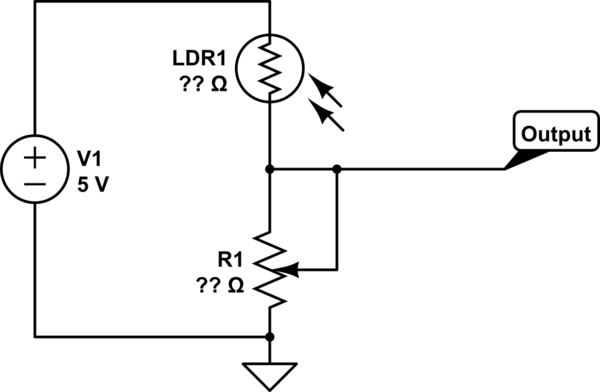
potentiometer Making an adjustable resistance
This part of the circuit is isolated from any other component, except for the 5V and ground connections. It includes LEDs and a shift register, which may not interact significantly. The LDR (Light Dependent Resistor) is utilized solely as a...
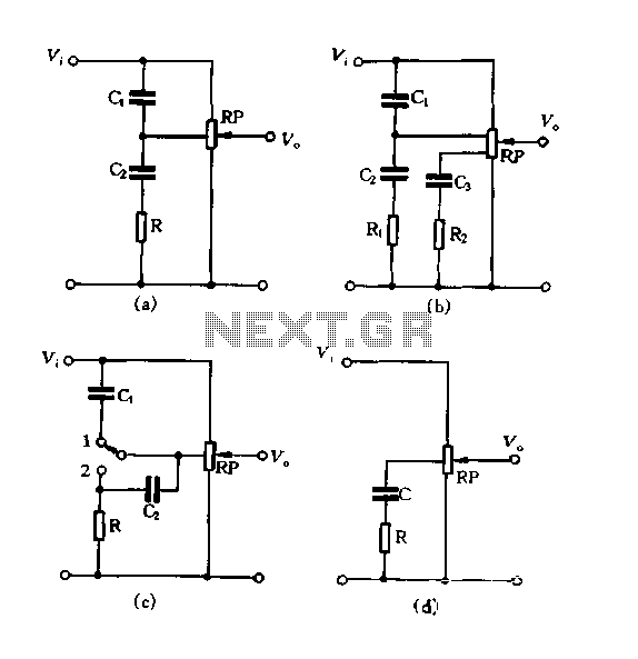
Using tap potentiometer loudness circuit
Figure 1.88 illustrates the loudness control circuit utilizing multiple taps on a potentiometer. In Figure (A), the connection is made between the tap and the potentiometer's input, along with the ground. An RC compensation network is employed, where the slide...
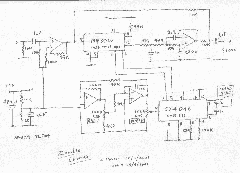
Zombie Chorus Guitar effect
This is my reincarnation of the EH Small Clone and Roland CE-1. Unlike the Clone it has a proper depth control. It also has a switch to change between the CE-1 like 512 stage delay and the Clone's 1024 stage...
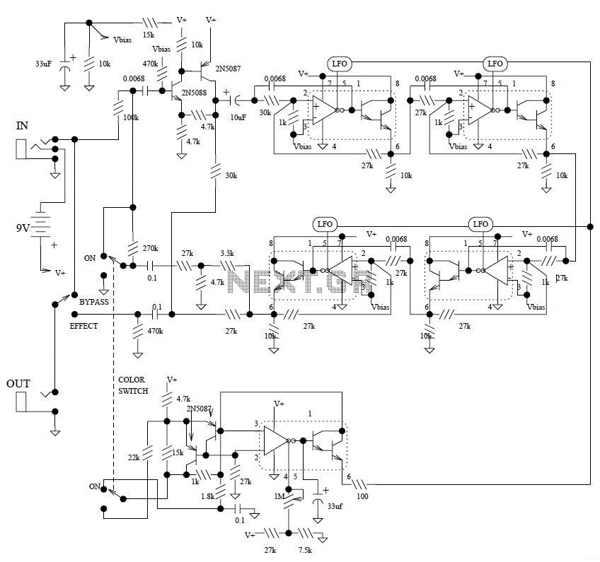
Electro-Harmonix Small Stone Phaser Guitar Effect
This is the schematic diagram of the Electro-Harmonix Small Stone Phaser guitar effect pedal. The Small Stone is notable for using Operational Transconductance Amplifiers (OTAs) for phase shift stages instead of traditional operational amplifiers.
The Electro-Harmonix Small Stone Phaser is a...
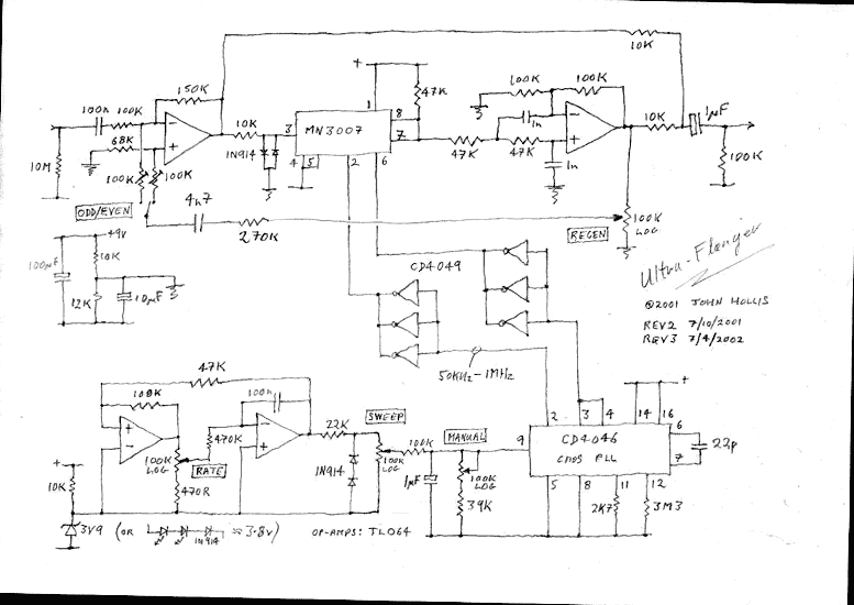
Ultra-Flanger guitar effect
I was originally going to develop a minimum part count version of the EH Electric Mistress. Instead I went for a something with the versatility of an MXR flanger and the extra wide sweep that the A/DA flanger was known...
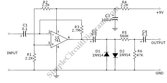
Fuzz Box Distortion Pedal Guitar Effect
This guitar effect circuit employs a straightforward high-gain amplification stage, succeeded by symmetric clipping achieved through a parallel diode clipper. The gain is provided by a 741 operational amplifier.
The circuit design begins with a high-gain amplification stage utilizing the 741...
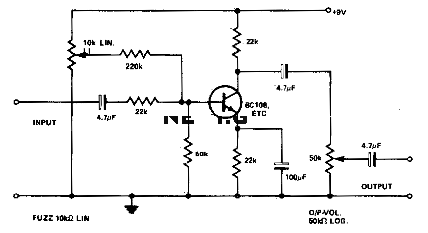
Fuzz box 4
None of the components are particularly critical in value or quality, as distortion is the sole object. The transistor could be BC107, BC108, BC109, 2N2926, etc.
The circuit in question is designed primarily to achieve distortion, which suggests it is likely...