


Guitar Vibrato circuit
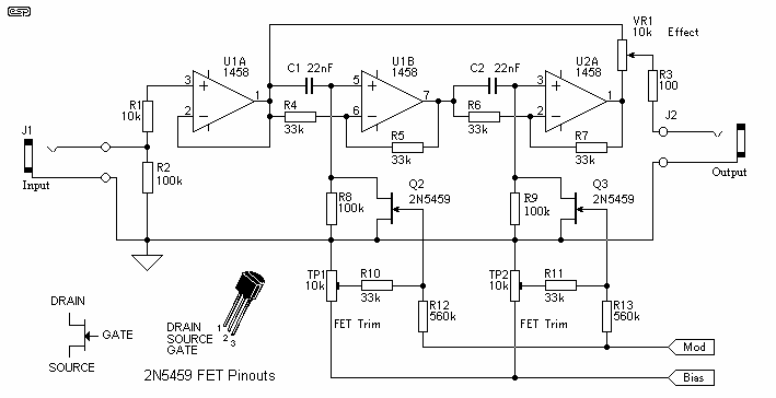
Description: The circuit of the unit is fairly simple, but is a bit irksome to set up. The reason is that obtaining matched FETs is not easy, so I had to make sure that the circuit would work with off-the-shelf FETs. The phase shifter is a standard opamp circuit, and has been used for this sort of application many times. After experimenting with alternative variable resistors, I decided that the FET was still the best choice, although they are fairly critical to set up, and have linearity problems. More: The circuit is conventional, except for the EFFECT control. With this, you can select the clean signal direct from the buffer stage, the fully phase (and hence frequency) modulated signal from the output of U2A, or a mixture of the two. With the pot centr
The circuit described consists of a phase shifter utilizing operational amplifiers (op-amps) and field-effect transistors (FETs) to manipulate the phase of an audio signal. The design aims to accommodate the challenges associated with sourcing matched FETs, which are essential for maintaining consistent performance in phase shifting applications. The circuit is structured to work with readily available, off-the-shelf FETs, enhancing its accessibility for practical implementation.
At the core of the circuit is a standard op-amp configuration, which serves as the primary mechanism for phase manipulation. The op-amp is configured in a feedback loop that allows for precise control of the phase shift introduced to the input signal. The choice of FETs in the circuit is critical, as they are employed for their variable resistance characteristics, which are necessary for achieving the desired modulation effects. However, the setup process can be intricate due to the sensitivity of FETs to variations in parameters such as temperature and biasing conditions, which can lead to linearity issues.
The circuit features an EFFECT control, which is a unique aspect that provides flexibility in signal processing. This control allows the user to select between three distinct output options: a clean signal directly from the buffer stage, a fully phase-modulated signal from the output of the second op-amp (U2A), or a blended output that combines both the clean and modulated signals. This capability enables users to tailor the output to their specific needs, whether for pure signal processing or for creative modulation effects.
In summary, the circuit is designed to be conventional in its operation while incorporating an innovative control feature that enhances its functionality. The careful selection of components, particularly the FETs, is essential for achieving the desired performance, making it a useful tool for audio signal processing applications.The circuit of the unit is fairly simple, but is a bit irksome to set up. The reason is that obtaining matched FETs is not easy, so I had to make sure that the circuit would work with off-the-shelf FETs. The phase shifter is a standard opamp circuit, and has been used for this sort of application many times.
After experimenting with alternative variable resistors, I decided that the FET was still the best choice, although they are fairly critical to set up, and have linearity problems. The circuit is conventional, except for the EFFECT control. With this, you can select the clean signal direct from the buffer stage, the fully phase (and hence frequency) modulated signal from the output of U2A, or a mixture of the two. With the pot centr
The circuit described consists of a phase shifter utilizing operational amplifiers (op-amps) and field-effect transistors (FETs) to manipulate the phase of an audio signal. The design aims to accommodate the challenges associated with sourcing matched FETs, which are essential for maintaining consistent performance in phase shifting applications. The circuit is structured to work with readily available, off-the-shelf FETs, enhancing its accessibility for practical implementation.
At the core of the circuit is a standard op-amp configuration, which serves as the primary mechanism for phase manipulation. The op-amp is configured in a feedback loop that allows for precise control of the phase shift introduced to the input signal. The choice of FETs in the circuit is critical, as they are employed for their variable resistance characteristics, which are necessary for achieving the desired modulation effects. However, the setup process can be intricate due to the sensitivity of FETs to variations in parameters such as temperature and biasing conditions, which can lead to linearity issues.
The circuit features an EFFECT control, which is a unique aspect that provides flexibility in signal processing. This control allows the user to select between three distinct output options: a clean signal directly from the buffer stage, a fully phase-modulated signal from the output of the second op-amp (U2A), or a blended output that combines both the clean and modulated signals. This capability enables users to tailor the output to their specific needs, whether for pure signal processing or for creative modulation effects.
In summary, the circuit is designed to be conventional in its operation while incorporating an innovative control feature that enhances its functionality. The careful selection of components, particularly the FETs, is essential for achieving the desired performance, making it a useful tool for audio signal processing applications.The circuit of the unit is fairly simple, but is a bit irksome to set up. The reason is that obtaining matched FETs is not easy, so I had to make sure that the circuit would work with off-the-shelf FETs. The phase shifter is a standard opamp circuit, and has been used for this sort of application many times.
After experimenting with alternative variable resistors, I decided that the FET was still the best choice, although they are fairly critical to set up, and have linearity problems. The circuit is conventional, except for the EFFECT control. With this, you can select the clean signal direct from the buffer stage, the fully phase (and hence frequency) modulated signal from the output of U2A, or a mixture of the two. With the pot centr
FET VOLTMETER
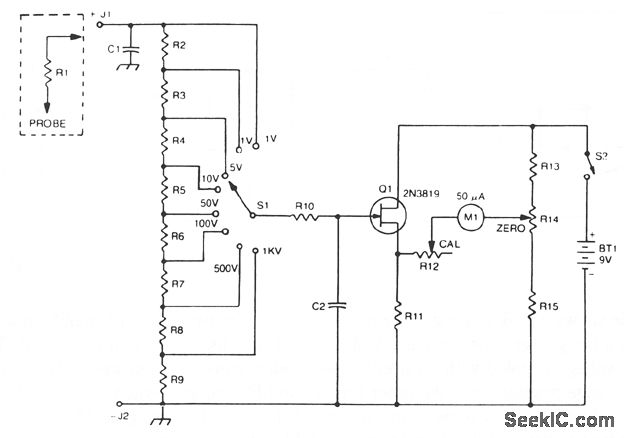
The 2N3819 FET serves as a solid-state voltage output meter (VOM). In this configuration, the 2N3819 functions as a cathode follower. The bias offset, or meter null, is achieved using resistors R14 and R12, while the full-scale calibration is set...
FET several basic bias circuit - self bias voltage divider circuit
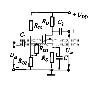
FET several basic bias circuit - self-bias voltage divider circuit
The self-bias voltage divider circuit is a fundamental configuration used in Field Effect Transistor (FET) biasing. This circuit employs two resistors to create a stable bias voltage for the transistor's gate,...
FET VOLTMETER 1
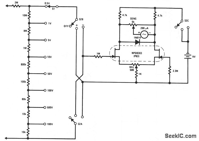
This FET voltmeter (FETVM) serves as a replacement for the vacuum tube voltmeter (VTVM) and eliminates the need for a standard line cord. Additionally, the drift rates of field-effect transistors (FETs) are significantly better than those of vacuum tube circuits,...
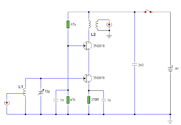
Band 2 Preamplifier
The lower FET operates in common source mode, while the upper FET operates in common gate mode, achieving full high-frequency gain. The bottom FET is tunable, allowing for peak adjustment for a particular station. Coil details follow:
The described circuit employs...
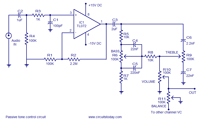
A quality tone control circuit using opamp and few passive components
Tone control circuit utilizing an operational amplifier and a Baxandall passive tone control configuration. The overall gain is 25 dB, with a boost and cut capability of 20 dB. The circuit is powered by a dual 15V supply.
The tone control...
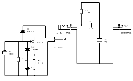
fet amp circuit
The gate-source voltage required to bias the transistor into the linear region can range from 0.25V to 8V, resulting in a potential variation of 7.75V down to a minimal 0.4V for the transistor and load when used with a typical...
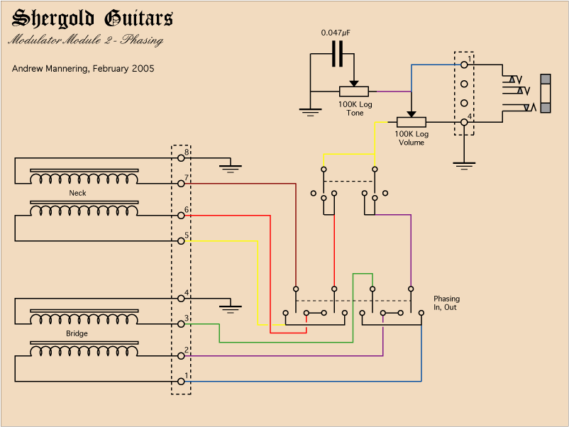
Guitars Modulator
Even with the controls set to their maximum position, there will always be some signal leakage, resulting in a loss of tone. With Module 3, engaging the bypass switch to 'Solo' disconnects the tone and volume controls from the circuit,...
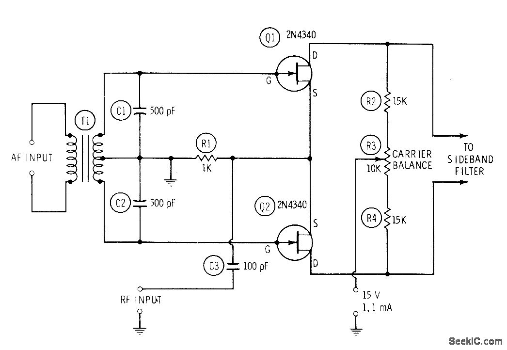
FET BALANCED MODULATOR FOR SSB
An audio frequency (AF) modulating signal is applied to the gates of matched field-effect transistors (FETs) configured in a push-pull arrangement via transformer T1, which features an accurately center-tapped secondary winding. The radio frequency (RF) carrier is simultaneously fed to...
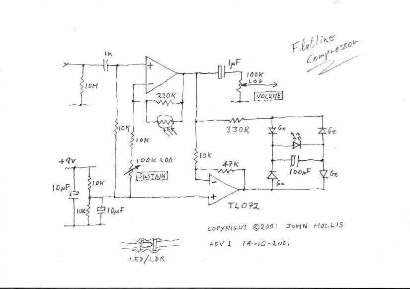
Guitar Flatline Compressor effect
This circuit is a simple, low noise guitar compressor.
The described circuit functions as a low-noise compressor specifically designed for guitar applications. It aims to reduce the dynamic range of the guitar signal, thereby allowing for a more consistent output level...