


Gyraf Audio EQ
#equalizer
#audio processing
#Calrec PQ1549
#IC-based
#DIY audio
#sound engineering
#music production
#analog audio
#studio equipment
#EQ circuit
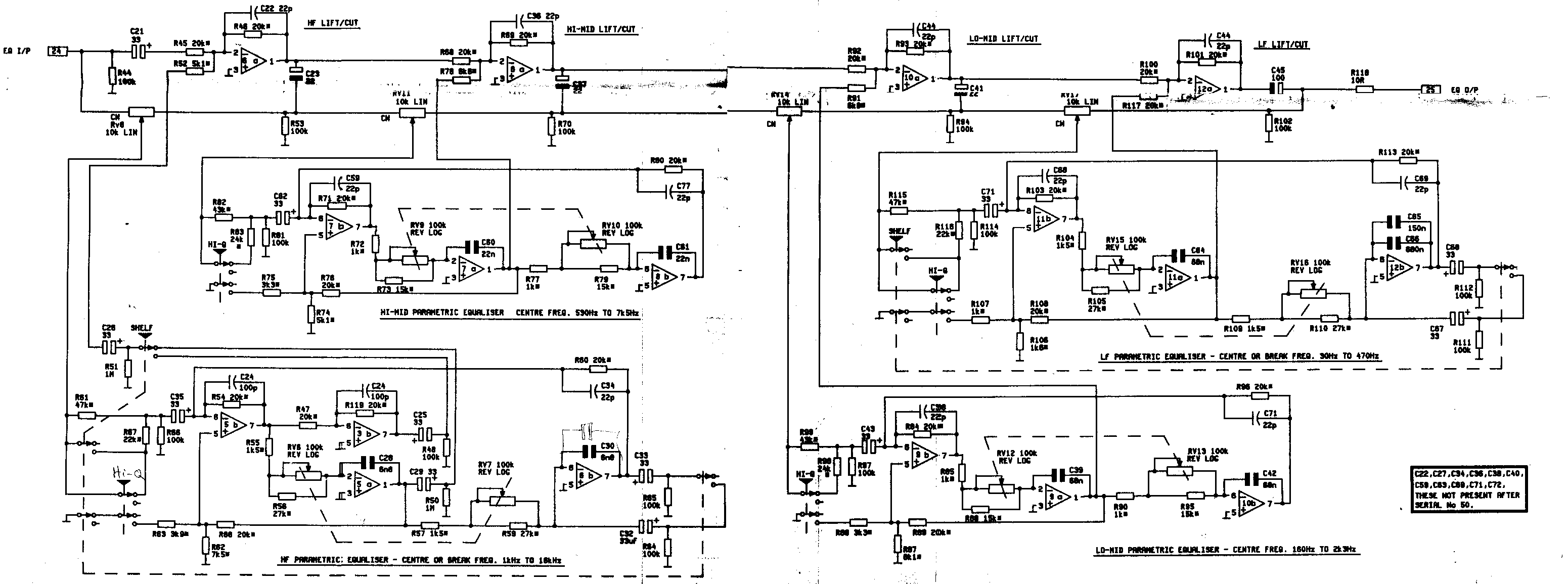
Description: This page contains information about constructing a personal version of the Calrec PQ1549 Equalizer, originally found in the Calrec "Polar" desk. This equalizer is highly regarded among standard IC-based types, prompting the creation of this project to allow more individuals to experience its qualities. Updates to this page will occur regularly, depending on the interest shown in its topics. Feedback and corrections are welcomed, though responses to all inquiries cannot be guaranteed. Contributors who undertake this project and document their process on their own webpage may receive a link here to benefit others from their experiences. All provided information, schematics, layouts, etc., are supplied "as is," and there is no liability for accuracy, functionality, or safety. Gyraf Audio disclaims any liability for losses, damages, or expenses arising from reliance on the information or services provided through this website. Caution is advised when working with mains voltages, as they can be lethal. The smallest error may have catastrophic consequences. The intent is to ensure safety while fostering an interest in building retro pro-audio equipment. The Calrec PQ1549 is a classic parametric equalizer from the Calrec "Polar" desk, of which fewer than 15 units are believed to remain worldwide. This adaptation of the original Calrec PQ1549 module utilizes components and parts that are widely available, excluding the mic preamp, filters, and switching. It incorporates newer op-amps, an electronically balanced input and output, and a hardwired bypass switch. Although some may prefer the mic amplifier, the necessary components are often difficult to obtain, thus the focus is on the raw EQ section.
The redrawn schematic begins with a standard debalancing input buffer that converts the balanced input signal to unbalanced, feeding into a series of four amplifiers, each connected to its respective filter section, and finally rebalancing the output. The four inverting add/subtract amplifiers operate in series, with the filter inputs connected to either the stage input (at maximum boost) or the inverted stage output (at maximum cut). When the dB+/- pots are centered, the normal and inverted signals cancel each other out, resulting in no signal being applied to the filter section input. The outputs from the filter sections are combined with the inverting inputs of the amplifier stages, effectively boosting or cutting any frequency that the filter sections allow through.
The four filter stages employ standard state-variable filters, with frequency control provided by a 2x100K negative logarithmic potentiometer, which is the only component that may be challenging to procure. The "Q" factor is switchable between high and low, with the switching also controlling filter gain to maintain a constant gain-versus-Q relationship. The "Shelving" switches on the low and high ends also bypass the "Q" switch. The PCB design for the PQ1549 consists of two 100x160mm eurocard PCBs that are interconnected. These single-sided PCBs accommodate all switches and pots, minimizing wiring to input, output, and power supply connections. The artwork files are in PDF format to preserve scale. It is important to note that the PCB (copper) side is drawn in a mirrored format to facilitate closer printout-to-photoresist contact during PCB fabrication. In case of uncertainty, the text on the board should serve as a reference.This pages contain information about building your own version of the Calrec PQ1549 Equalizer, the one found in the Calrec "Polar" desk. This EQ is one of my absolute favorites when it comes to standard IC-based types, so I made this project to make it possible for more people to experience these qualities.
I will try to update this page reguarly if anyone shows interest in its topics. Comments and corrections are welcome, but I can`t promise to reply to all mail. If you do this project and describe the process on your webpage, I`ll be more than happy to add a link here, so others can benefit from your experiences. Notice that all information, schematics, layouts etc. are supplied "as is", and that we can in no way be held responsible for its acurateness, functionality or even safety.
Gyraf Audio shall not be responsible and disclaims all liability for any loss, liability, damage (whether direct or consequential) or expense of any nature whatsoever which may be suffered as a result of or which may be attributable, directly or indirectly, to the use of or reliance upon any information, links or service provided through this website. Also you should take extreme caution when working with mains voltages. These voltages are lethal, and the smallest error will be chatastrophic. And we like you to stay alive and well, so you can help other people sharing our bizarre interest for building retro-pro-audio-equipment.
The Calrec PQ1549 is a classic no-nonsense parametric equalizer from the famous (and huge!) Calrec "Polar" desk, that were only manufactured in very small numbers. I believe that there`s less than 15 desks like this left worldwide. This is an adaption of the original Calrec PQ1549 module to components and parts that are available (hopefully) everywhere.
Adaption includes removal of the mic preamp, filters and switching, changing to newer and even better opamps, adding electronically balanced input and output and a hardwired bypass switch. No doubt that some of you would have liked the Micamp and all, but these imply quite a few not-so-easy-to-get components.
So I`m going for the raw EQ section. Looking on the redrawn schematic, we first have a standard debalancing input buffer, converting our balanced input signal to unbalanced, and feeding a series of four amplifiers connected one to each` own filter section, and finally balanced again for the output. The four inverting add/subtract amplifiers - working in series - has the filters` inputs connected to either the stage input (at max.
boost) or to the inverted stage output (at max cut). Keeping in mind, that the output from each stage is a inverted replica of the input, it`s easy to see that when the dB+/- pots are in their centre positions, the normal and inverted signals cancels out, and no signal is applied to the filter section input. The output from the filter sections are added in with the inverting inputs of the amplifier stages, effectively boosting or cutting any frequency that the filter sectionlets through.
The four filter stages are - more or less - standard state variable filters. Their frequency is controlled by a 2x100K negative logaritmic potentiometer, which is the only "hard to get" component in this design. The "Q" factor is switchable high or low, the switching also controlling filter gain to acheive a constant gain-versus-Q.
The "Shelving" switches on the low and high end also bypasses the "Q" switch. The PCB set for the PQ1549 consists of two 100x160mm "eurocard" pcb`s, that are interconnected. The PCB`s are single-sided, and carry all switches and pots, limiting wireing to input, output and PSU. The artwork files are in PDF format to maintain scale. Please note that the PCB (copper) side is drawn MIRROR`ED - enabling closer printout-to-photoresist contact when making the PCB.
If in doubt, use the text on the board as reference.
The redrawn schematic begins with a standard debalancing input buffer that converts the balanced input signal to unbalanced, feeding into a series of four amplifiers, each connected to its respective filter section, and finally rebalancing the output. The four inverting add/subtract amplifiers operate in series, with the filter inputs connected to either the stage input (at maximum boost) or the inverted stage output (at maximum cut). When the dB+/- pots are centered, the normal and inverted signals cancel each other out, resulting in no signal being applied to the filter section input. The outputs from the filter sections are combined with the inverting inputs of the amplifier stages, effectively boosting or cutting any frequency that the filter sections allow through.
The four filter stages employ standard state-variable filters, with frequency control provided by a 2x100K negative logarithmic potentiometer, which is the only component that may be challenging to procure. The "Q" factor is switchable between high and low, with the switching also controlling filter gain to maintain a constant gain-versus-Q relationship. The "Shelving" switches on the low and high ends also bypass the "Q" switch. The PCB design for the PQ1549 consists of two 100x160mm eurocard PCBs that are interconnected. These single-sided PCBs accommodate all switches and pots, minimizing wiring to input, output, and power supply connections. The artwork files are in PDF format to preserve scale. It is important to note that the PCB (copper) side is drawn in a mirrored format to facilitate closer printout-to-photoresist contact during PCB fabrication. In case of uncertainty, the text on the board should serve as a reference.This pages contain information about building your own version of the Calrec PQ1549 Equalizer, the one found in the Calrec "Polar" desk. This EQ is one of my absolute favorites when it comes to standard IC-based types, so I made this project to make it possible for more people to experience these qualities.
I will try to update this page reguarly if anyone shows interest in its topics. Comments and corrections are welcome, but I can`t promise to reply to all mail. If you do this project and describe the process on your webpage, I`ll be more than happy to add a link here, so others can benefit from your experiences. Notice that all information, schematics, layouts etc. are supplied "as is", and that we can in no way be held responsible for its acurateness, functionality or even safety.
Gyraf Audio shall not be responsible and disclaims all liability for any loss, liability, damage (whether direct or consequential) or expense of any nature whatsoever which may be suffered as a result of or which may be attributable, directly or indirectly, to the use of or reliance upon any information, links or service provided through this website. Also you should take extreme caution when working with mains voltages. These voltages are lethal, and the smallest error will be chatastrophic. And we like you to stay alive and well, so you can help other people sharing our bizarre interest for building retro-pro-audio-equipment.
The Calrec PQ1549 is a classic no-nonsense parametric equalizer from the famous (and huge!) Calrec "Polar" desk, that were only manufactured in very small numbers. I believe that there`s less than 15 desks like this left worldwide. This is an adaption of the original Calrec PQ1549 module to components and parts that are available (hopefully) everywhere.
Adaption includes removal of the mic preamp, filters and switching, changing to newer and even better opamps, adding electronically balanced input and output and a hardwired bypass switch. No doubt that some of you would have liked the Micamp and all, but these imply quite a few not-so-easy-to-get components.
So I`m going for the raw EQ section. Looking on the redrawn schematic, we first have a standard debalancing input buffer, converting our balanced input signal to unbalanced, and feeding a series of four amplifiers connected one to each` own filter section, and finally balanced again for the output. The four inverting add/subtract amplifiers - working in series - has the filters` inputs connected to either the stage input (at max.
boost) or to the inverted stage output (at max cut). Keeping in mind, that the output from each stage is a inverted replica of the input, it`s easy to see that when the dB+/- pots are in their centre positions, the normal and inverted signals cancels out, and no signal is applied to the filter section input. The output from the filter sections are added in with the inverting inputs of the amplifier stages, effectively boosting or cutting any frequency that the filter sectionlets through.
The four filter stages are - more or less - standard state variable filters. Their frequency is controlled by a 2x100K negative logaritmic potentiometer, which is the only "hard to get" component in this design. The "Q" factor is switchable high or low, the switching also controlling filter gain to acheive a constant gain-versus-Q.
The "Shelving" switches on the low and high end also bypasses the "Q" switch. The PCB set for the PQ1549 consists of two 100x160mm "eurocard" pcb`s, that are interconnected. The PCB`s are single-sided, and carry all switches and pots, limiting wireing to input, output and PSU. The artwork files are in PDF format to maintain scale. Please note that the PCB (copper) side is drawn MIRROR`ED - enabling closer printout-to-photoresist contact when making the PCB.
If in doubt, use the text on the board as reference.
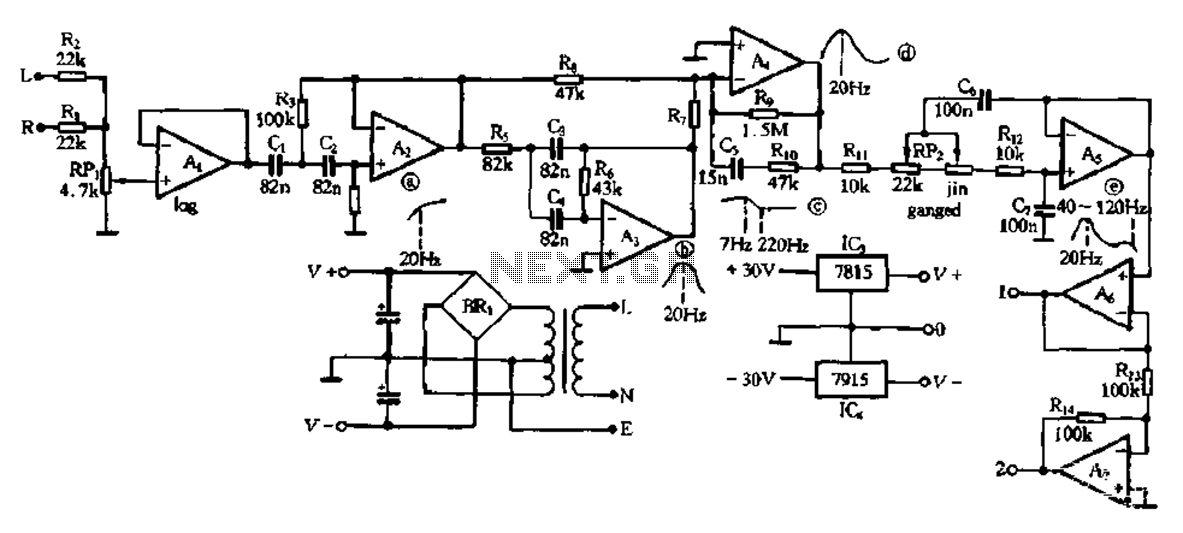
Electronic type bass equalization circuit
This electronic bass equalizer circuit utilizes two quad operational amplifiers, specifically the TL084 high-speed operational amplifier. The circuit includes left and right channels that are mixed through resistors R1 and R2, and features a total bass level adjustment potentiometer designed...
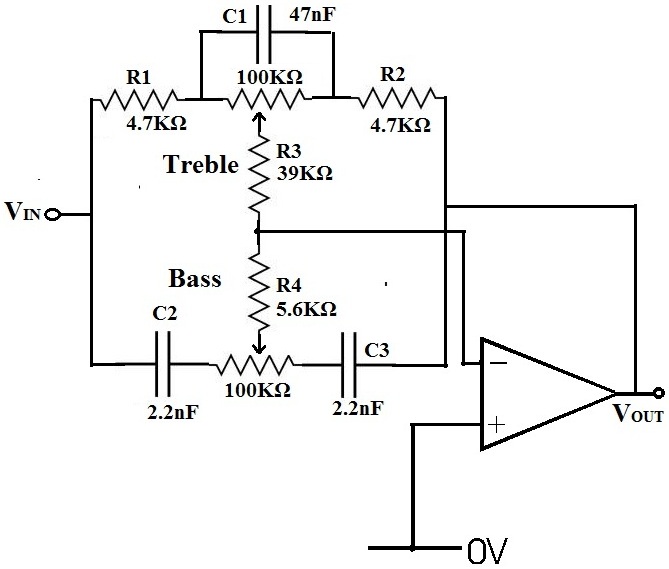
Audio Equalizer
An equalizer is a device that allows for the adjustment of the gains of individual frequencies. For instance, to reduce bass, one would navigate to the frequency range around 500Hz and decrease the volume. Conversely, to enhance treble, one would...
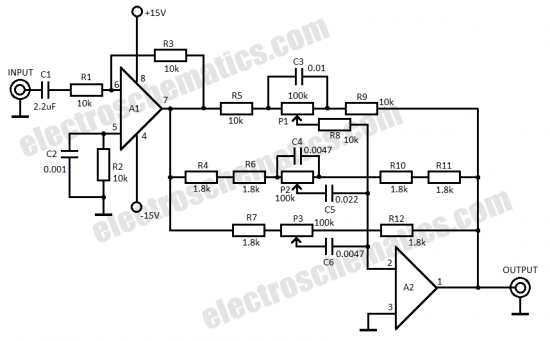
3 band equalizer circuit
This three-band equalizer circuit functions as an active filter network for bass, mid, and high audio frequencies. It is built around the LM833 operational amplifier from National Semiconductors. The output of this three-way graphic equalizer is configured to be DC...
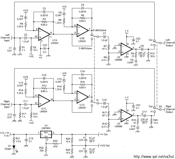
ARRL Handbook Audio Intelligibility Enhancer
Assistance is sought for building the N4GG audio intelligibility enhancer project as detailed in the ARRL Handbook. A circuit board has been ordered from Far Circuits, but there are difficulties in sourcing the necessary components. Attempts have been made to...
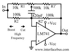
Audio Equalizer Circuits
This discussion continues from the audio tone control topic, which introduced both passive and active tone controls. The follow-up topics may include a 2-Band Active Tone Control or a 3-Band Active Tone Control. An audio equalizer is utilized to adjust...

Ten-Band Equalizer
The equalizer discussed in this article is appropriate for use with high-fidelity installations, public address systems, mixers, and electronic musical instruments.
The equalizer is an essential audio processing device that allows for the adjustment of specific frequency bands within an audio...
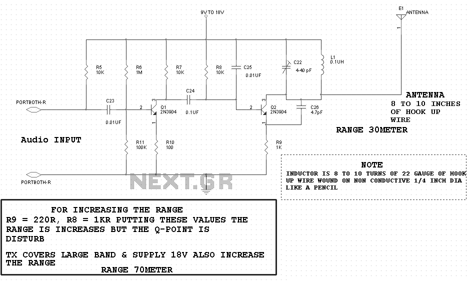
Music Equalizer Display Circuit
The music equalizer display schematic is relatively straightforward to construct. It can be assembled on a compact breadboard, utilizing the components listed previously. Due to the high number of connections required, it is advisable to have an ample supply of...
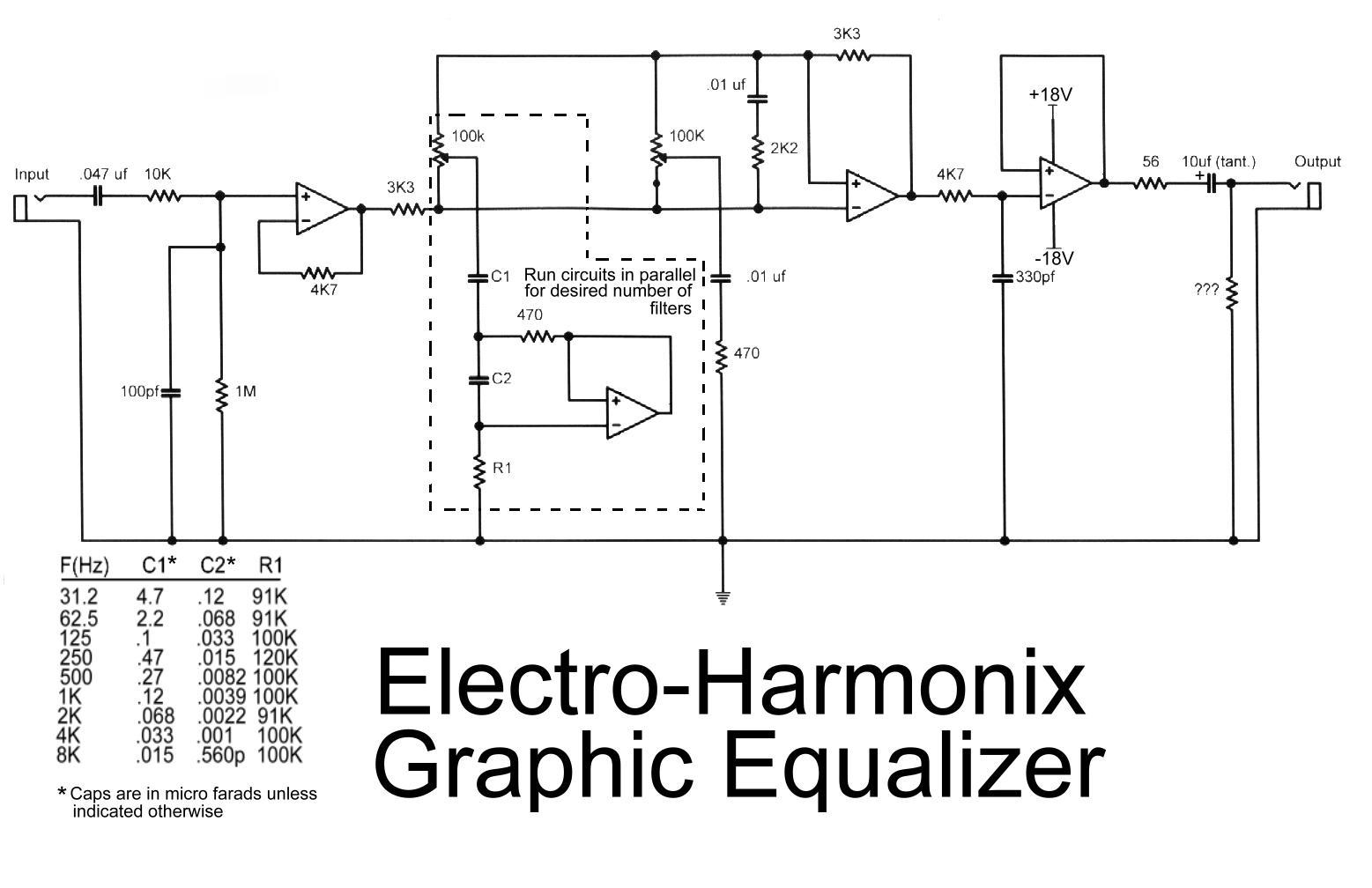
Electro harmonix graphic equalizer circuit
This is the diagram of the Electro-Harmonix graphic equalizer. The number of channels can be specified according to requirements by paralleling the components: C1, C2, R1, an operational amplifier, potentiometer, and a 470-ohm resistor. The frequency to be boosted is...
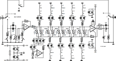
10 band equalizer
The equalizer described is designed for hi-fi installations, public address systems, mixers, and electronic musical instruments. Relay contacts at the inputs and outputs, in conjunction with switch S2, allow for the selection of the desired channel. The input can be...