


lets to build mini organ keyboard
#UM3511-IC
#transistor
#speaker
#oscillator
#variable resistor
#frequency adjustment
#keyboard
#sound generation
#switch
#audio output

Description: The output of pin 5 on the UM3511 integrated circuit can be connected to drive a transistor, which will emit loud sounds through speakers directly. The variable resistor (VR1) determines the frequency of the oscillator circuit and should be adjusted to the correct value once the circuit is successfully created. After adjustment, a standard resistor may be used instead. The switch (S1) serves as an option that controls the operation of the circuit. Music can be played either from the factory application or from personal input via a keyboard, producing various notes.
The UM3511 is a sound generator IC designed for generating audio tones. By connecting pin 5 to a transistor, a robust output can be achieved to drive speakers effectively. The transistor acts as a switch, amplifying the signal from the UM3511 to a level suitable for driving speakers, ensuring that the sound output is loud and clear.
The variable resistor (VR1) plays a crucial role in setting the frequency of the oscillator circuit within the UM3511. By adjusting VR1, the user can modify the pitch of the sound generated. This adjustment is essential for achieving the desired audio output, and once the correct frequency is determined, a fixed resistor can replace the variable resistor for stability in the circuit.
The inclusion of switch S1 provides flexibility in operation. This switch allows the user to select between different modes of sound generation. In one mode, the circuit can play pre-programmed music from the factory settings of the UM3511. In another mode, the user can input their own melodies using a keyboard, allowing for creativity and personalization in sound production. The keyboard interface can be designed to send signals corresponding to different notes, which the UM3511 interprets to produce sound.
Overall, this circuit design offers a versatile platform for sound generation, making it suitable for various applications, including educational projects, musical instruments, and sound effects in electronic devices. Proper component selection and circuit layout will ensure optimal performance and sound quality.We can connect a output of pin 5 on the UM3511-IC to drive a transistor output to emit loud sound out to the speakers directly. For the variable resistor-VR1 act as determine a frequency of the oscillator circuit. When we created successfully. Should be adjusted to the correct value. When adjusted, you may use the normal resistor instead. -The switch-S1 as an option act the work of circuit that music will be played by the application of the factory, or will play music as we have played own. From pushing keyboard as by various notes.
The UM3511 is a sound generator IC designed for generating audio tones. By connecting pin 5 to a transistor, a robust output can be achieved to drive speakers effectively. The transistor acts as a switch, amplifying the signal from the UM3511 to a level suitable for driving speakers, ensuring that the sound output is loud and clear.
The variable resistor (VR1) plays a crucial role in setting the frequency of the oscillator circuit within the UM3511. By adjusting VR1, the user can modify the pitch of the sound generated. This adjustment is essential for achieving the desired audio output, and once the correct frequency is determined, a fixed resistor can replace the variable resistor for stability in the circuit.
The inclusion of switch S1 provides flexibility in operation. This switch allows the user to select between different modes of sound generation. In one mode, the circuit can play pre-programmed music from the factory settings of the UM3511. In another mode, the user can input their own melodies using a keyboard, allowing for creativity and personalization in sound production. The keyboard interface can be designed to send signals corresponding to different notes, which the UM3511 interprets to produce sound.
Overall, this circuit design offers a versatile platform for sound generation, making it suitable for various applications, including educational projects, musical instruments, and sound effects in electronic devices. Proper component selection and circuit layout will ensure optimal performance and sound quality.We can connect a output of pin 5 on the UM3511-IC to drive a transistor output to emit loud sound out to the speakers directly. For the variable resistor-VR1 act as determine a frequency of the oscillator circuit. When we created successfully. Should be adjusted to the correct value. When adjusted, you may use the normal resistor instead. -The switch-S1 as an option act the work of circuit that music will be played by the application of the factory, or will play music as we have played own. From pushing keyboard as by various notes.

Six a start and stop intermittent cycle control circuits
The circuit illustrated in Figure 3-81 employs a transistor delay circuit to facilitate start-stop cycle control. It can operate in both manual and automatic modes. The circuit is primarily governed by the motor run time circuit, which includes transistors VTi...
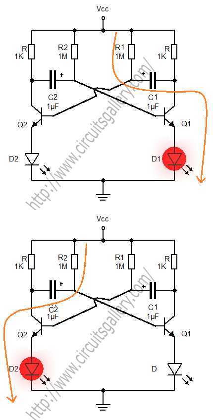
Astable Multivibrator
A transistorized astable multivibrator is a cross-coupled transistor network capable of generating a continuous square wave. It operates as a free-running oscillator or a regenerative switching circuit that utilizes positive feedback. The astable multivibrator continuously alternates between its two unstable...
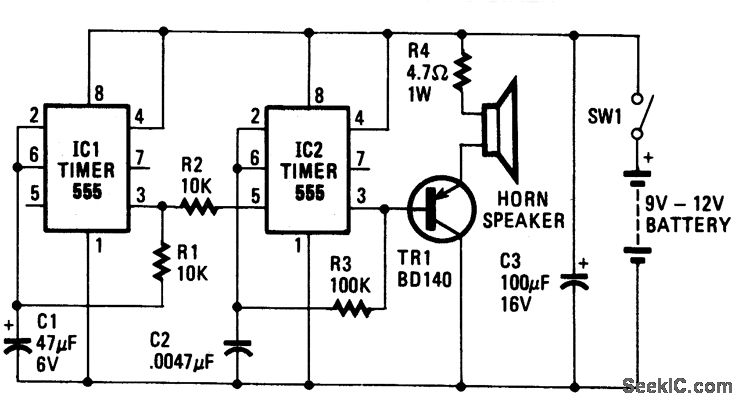
HEE HAW ELECTRONIC SIREN
The oscillator based on IC2 generates sound, with its output linked to the base of TR1, which amplifies the signal to drive the speaker. Resistor R4 is included to limit the current through TR1 to a safe level. The oscillation...

Kapanadze 5
The emitter voltage drops completely to 0V from 42V during the pulse when the transistor is conducting or saturated. This contrasts with a pure resistive load (the 4.7 Ohm resistor mentioned in the previous video), where the collector-emitter voltage does...
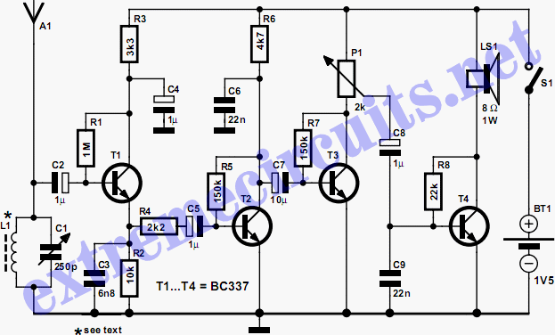
Economical Transistor Radio
The schematic diagram illustrates an audio stage utilizing a common-collector circuit. This configuration does not dampen the tuned circuit; rather, it enhances its response, resulting in improved sensitivity and selectivity. Due to the low supply voltage, the subsequent audio amplifier...
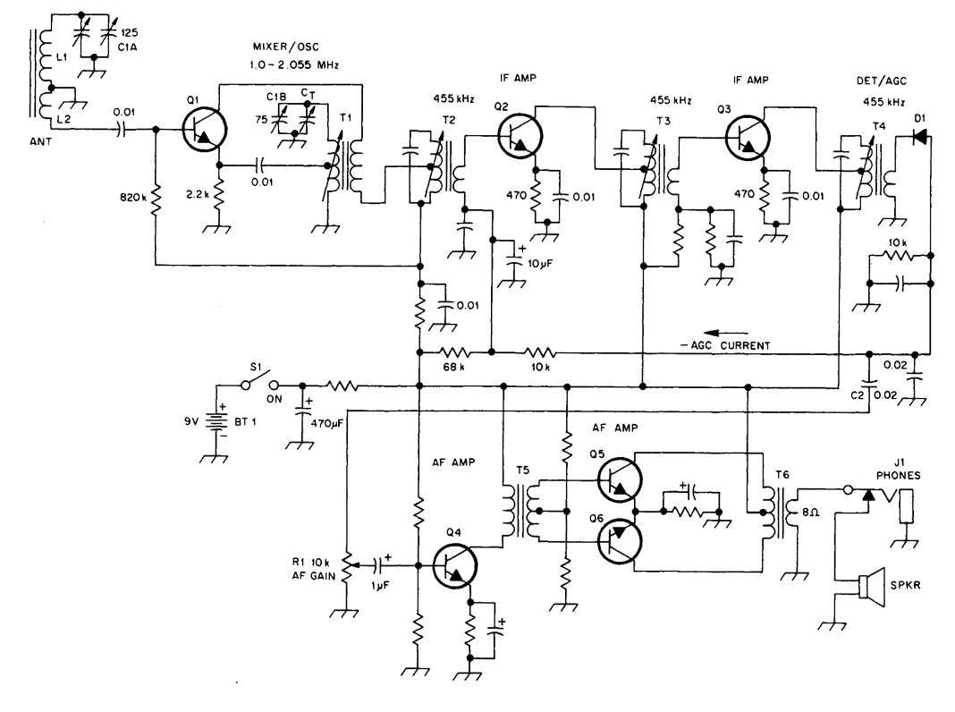
TRANSISTORIZED AM RADIO
The schematic illustrates a standard AM radio circuit utilizing NPN transistors. This generic circuit does not provide specific values for all components, serving instead as a reference point for experimenters to begin their projects.
The schematic of a typical transistor AM...
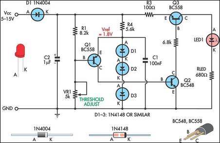
Low Supply Rail Detection
This is a simple low supply rail detection circuit that is inexpensive and can be assembled in approximately 20 minutes. Its low power consumption makes it suitable for integration into battery-powered devices. Instead of utilizing an operational amplifier, the circuit...
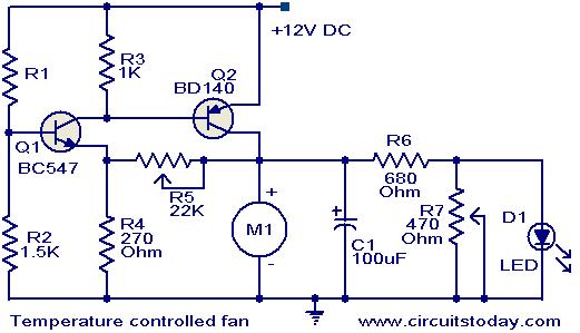
Temperature controlled DC fan
This circuit utilizes two transistors to regulate the speed of a 12 V DC fan based on temperature changes. A thermistor (R1) detects the temperature. As the temperature rises, the base current of transistor Q1 (BC 547) increases, leading to...
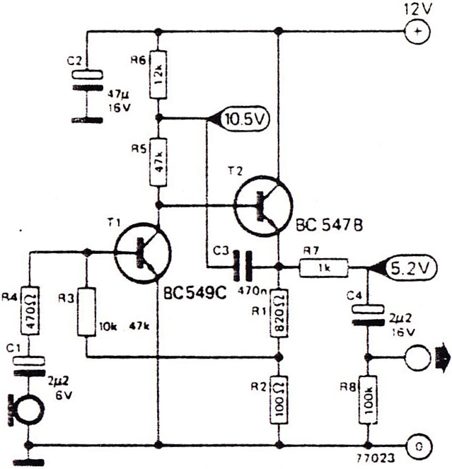
portable mic pre amp 2 transistor
Portable microphone preamplifier using two transistors, BC549C and BC547B. The electret condenser microphone or microphone's dynamic range is very sensitive.
The portable microphone preamplifier circuit utilizes two transistors, BC549C and BC547B, to amplify the low-level audio signals from an electret condenser...