


LM386 making music with a voice-activated lights circuit
#LM386
#voice-activated
#lights
#amplifier
#voltage regulator
#rectifier
#capacitor
#step-down
#music
#sound
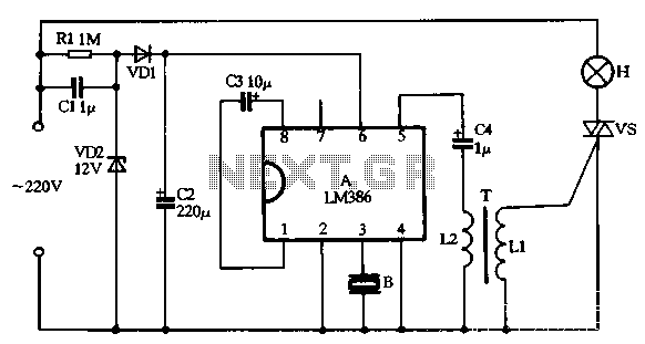
Description: VD1, VD2, C1, and C2 comprise a simple half-wave rectifier capacitor step-down voltage regulator circuit, providing an output of approximately 12V for a linear power supply connected to the LM386. The LM386 is linked to the inverting input terminal (pin 3) and interfaces with a piezoelectric ceramic sheet B, which receives environmental acoustic signals and converts them into corresponding electrical signals. The amplified output from the internal circuit appears at pin 5 and is coupled through C4 to a bidirectional thyristor (VS). The conduction angle of the thyristor is modulated based on the strength of the received signals, allowing for the lantern string H to emit flashing light in response to the strength of the acoustic environment.
The circuit functions as a basic power supply and signal processing unit. The half-wave rectifier formed by diodes VD1 and VD2, along with capacitors C1 and C2, provides a regulated DC voltage output suitable for powering the LM386 audio amplifier. This amplifier is specifically designed to operate with low-voltage power supplies and is capable of amplifying low-level audio signals from the piezoelectric sensor.
The piezoelectric ceramic sheet acts as a transducer, converting mechanical vibrations from the environment into electrical signals. When acoustic waves strike the piezoelectric material, it generates a voltage proportional to the intensity of the sound. This voltage is fed into the LM386, where it is amplified to a usable level.
The output from the LM386 (pin 5) is coupled through capacitor C4 to the gate of the thyristor. The thyristor's conduction angle is controlled by the amplified signal, effectively modulating the power delivered to the lantern string H. As the acoustic signal strength varies, the intensity and flash rate of the lantern's light output correspondingly change, creating a visual representation of the surrounding acoustic environment.
This circuit design is particularly useful in applications where visual indicators are needed to represent sound levels, such as in sound-activated lighting systems or audio-responsive decorations. The integration of the piezoelectric sensor with the LM386 amplifier and the thyristor control allows for a compact and efficient system capable of real-time response to environmental sounds.VD1, VD2, C1 and C2 form a simple half-wave rectifier capacitor step-down voltage regulator circuit, the output of about 12V in straight right current voltage supply manifold LM386 electricity. LM386 connected to the inverting input terminal 3 feet inside the piezoelectric ceramic sheet B receiving environment acoustic signal and converts it into a corresponding electrical signal, amplifying circuit after the internal manifold by 5 feet output by C4, T bidirectional drive thyristor vs, make vs conduction angle B with signals picked up strength and change, so can make the lantern string H with flashing light and acoustic environment signal strength.
The circuit functions as a basic power supply and signal processing unit. The half-wave rectifier formed by diodes VD1 and VD2, along with capacitors C1 and C2, provides a regulated DC voltage output suitable for powering the LM386 audio amplifier. This amplifier is specifically designed to operate with low-voltage power supplies and is capable of amplifying low-level audio signals from the piezoelectric sensor.
The piezoelectric ceramic sheet acts as a transducer, converting mechanical vibrations from the environment into electrical signals. When acoustic waves strike the piezoelectric material, it generates a voltage proportional to the intensity of the sound. This voltage is fed into the LM386, where it is amplified to a usable level.
The output from the LM386 (pin 5) is coupled through capacitor C4 to the gate of the thyristor. The thyristor's conduction angle is controlled by the amplified signal, effectively modulating the power delivered to the lantern string H. As the acoustic signal strength varies, the intensity and flash rate of the lantern's light output correspondingly change, creating a visual representation of the surrounding acoustic environment.
This circuit design is particularly useful in applications where visual indicators are needed to represent sound levels, such as in sound-activated lighting systems or audio-responsive decorations. The integration of the piezoelectric sensor with the LM386 amplifier and the thyristor control allows for a compact and efficient system capable of real-time response to environmental sounds.VD1, VD2, C1 and C2 form a simple half-wave rectifier capacitor step-down voltage regulator circuit, the output of about 12V in straight right current voltage supply manifold LM386 electricity. LM386 connected to the inverting input terminal 3 feet inside the piezoelectric ceramic sheet B receiving environment acoustic signal and converts it into a corresponding electrical signal, amplifying circuit after the internal manifold by 5 feet output by C4, T bidirectional drive thyristor vs, make vs conduction angle B with signals picked up strength and change, so can make the lantern string H with flashing light and acoustic environment signal strength.

Amplifier Cool-Down Circuit Circuit
This cool-down relay circuit utilizes an integrated circuit (IC) timer to control a relay, which maintains the operation of the blower for a specified time delay determined by timer U3. The capacitance value of C2 can be adjusted to either...
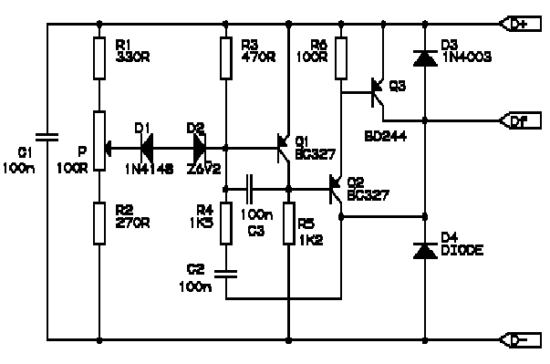
BMW R Series Motorcycle Regulator Schematic
Correctly adjusted, the voltage on the pot wiper is slightly less than half D+ (appx. 0.47*D+) and Q1 will conduct if (D+)-(Vp) > 6.2 + 0.7 + 0.7, or 0.53*(D+) > 7.6V, (D+) > 14.3V. If D+ is lower than...
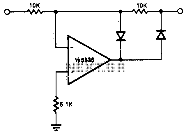
Half-wave rectifier
This circuit allows for precise half-wave rectification of the incoming signal. It exhibits a gain of 0 for positive signals and a gain of -1 for negative signals. By reversing the orientation of both diodes, the output polarity can be...
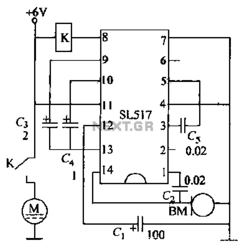
Voice-activated toy car circuit
Electric cars utilize a voice circuit principle, where sound signals are captured by a microphone (BM) and processed. The signal is then coupled through a capacitor to an integrated circuit (IC), which includes an internal amplifier that boosts the weak...
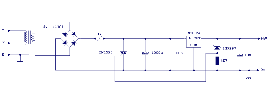
Logic PSU with Overvoltage Protection
The 5 volt regulated power supply for TTL and 74LS series integrated circuits has to be very precise and tolerant of voltage transients. These ICs are easily damaged by short voltage spikes. A fuse will blow when its current rating...
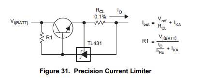
Capacitor Charging Circuit
This Korean SuperCap OEM supports usage in series configurations. Consider whether the implementation will be manual or automatic, such as with a smart battery charger or a power fail backup circuit. It is essential to balance the voltage and provide...
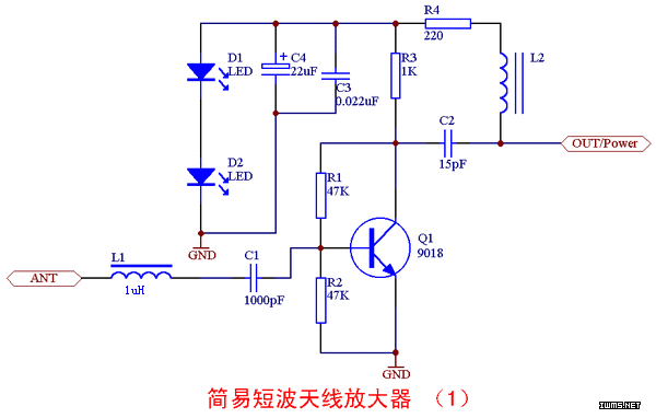
A simple and effective short-wave antenna amplifier circuit
This amplifier is designed for outdoor installation and is connected to an indoor power line box. It utilizes either 50-ohm or 75-ohm coaxial cables for the connection between indoor and outdoor units. The amplifier circuit board is depicted in Figures...
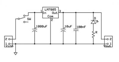
ic-7805 based 5V breadboard mini PSU circuit with explanation
A micro power supply unit (PSU) is designed to power a breadboard with a voltage output of 5 volts. It can be connected to a 9V battery, a 12V source, or any other direct current (DC) power supply ranging from...
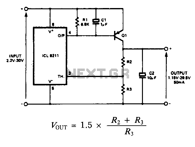
Positive-regulator-with-pnp-boost
The IC8211 serves as the voltage reference and regulator amplifier, with Q1 functioning as the series pass transistor. Resistor R1 defines the output current of the IC8211, while capacitors C1 and C2 ensure loop stability and help suppress the feedthrough...