


Many simple door buzzer sound circuits
#IC 555
#door buzzer
#loudspeaker
#9V battery
#sound circuit
#electric bell
#simple circuit
#buzzer sound
#low power
#economical
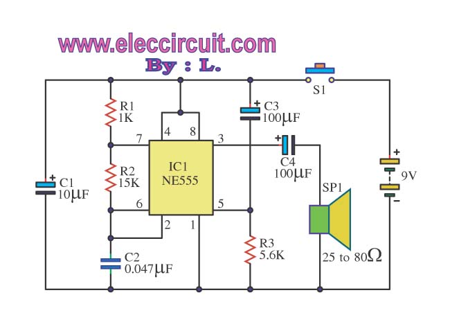
Description: The Door Buzzer circuit utilizes an IC 555 to generate a sound resembling an electric bell. When the switch S1 is pressed, a loud sound is produced. This circuit is designed to be simple and requires minimal components. It is recommended to use a loudspeaker with an impedance of 25-80 ohms to ensure good sound quality while maintaining low power consumption. A 9V battery can be used as the power source. The circuit employs an NE555 IC to create the bell sound, and an LM386 IC is used for amplification. A resistor R1 can be adjusted to modify the sound output. The circuit includes three potentiometers (VR1, VR2, and VR3), each rated at 1M ohm, to fine-tune the sound. The audio oscillator can be configured to produce a sine wave form, which can be activated by pressing S1. To enhance the sound further, a power amplifier is necessary, and the circuit requires a dual power supply setup with positive, ground, and negative connections, all powered by a 9V supply.
The Door Buzzer circuit is a straightforward yet effective electronic design that leverages the capabilities of the NE555 timer IC for sound generation and the LM386 audio amplifier for sound amplification. The NE555 timer operates in astable mode, producing a square wave output at pin 3, which mimics the ringing of a doorbell. The frequency of this output can be adjusted using the resistor R1 and the three potentiometers (VR1, VR2, VR3). Each potentiometer allows for individual control over the tone and volume, enabling the user to customize the sound to their preference.
The LM386 amplifier is connected to the output of the NE555 to boost the audio signal before it drives the speaker. This configuration ensures that the sound produced is loud enough to be heard clearly at a distance, making it suitable for a doorbell application. The choice of a loudspeaker with an impedance between 25-80 ohms ensures compatibility with the LM386 output, which is designed to drive such loads efficiently.
The circuit is powered by a 9V battery, providing a suitable voltage level for both the NE555 and the LM386. The requirement for a dual power supply with positive, ground, and negative connections allows for stable operation and minimizes noise in the audio output. Overall, this circuit is an excellent choice for those looking to create a simple and effective doorbell system with customizable sound features.Door Buzzer by use, IC 555. Perform sound electric bell origin. When press S1 as a result have a voice fair loud. This circuit almost must not do anything. Because divisible Amen! should use 25-80ohm size loudspeakers. will make good sound use force against electricity low work or economize the electricity. You will may use 9V batteries all right sir. Someday I goes to visit a friend. He begs me helps to seek electric bell front door circuit. In model to be simple, use the a little equipment. I then choose the Door Buzzer circuit this give. Because of use, IC NE555 produce electric bell sound and use IC LM386 for amplify talk at one time. For R1 use fine decorate the sound as you like it. request have fun this circuit. This is a basic electronic ell circuit, it is interesting. We use a number of IC-741 Op-amp, it works. When you press S1 will be mimic the bell sound at the output pin 6 of IC1, which we can fine tone sound with three potentiometer are VR1-1M, VR2-1M and VR3-1M to control sound as close as possible. We set form of the audio oscillator generator or sine wave form can be changed with by pressing our S1.
But sound is slight required to use power amplifier for boost up its. And this circuit need the dual power supply positive, ground, and negative 9V power supply.
The Door Buzzer circuit is a straightforward yet effective electronic design that leverages the capabilities of the NE555 timer IC for sound generation and the LM386 audio amplifier for sound amplification. The NE555 timer operates in astable mode, producing a square wave output at pin 3, which mimics the ringing of a doorbell. The frequency of this output can be adjusted using the resistor R1 and the three potentiometers (VR1, VR2, VR3). Each potentiometer allows for individual control over the tone and volume, enabling the user to customize the sound to their preference.
The LM386 amplifier is connected to the output of the NE555 to boost the audio signal before it drives the speaker. This configuration ensures that the sound produced is loud enough to be heard clearly at a distance, making it suitable for a doorbell application. The choice of a loudspeaker with an impedance between 25-80 ohms ensures compatibility with the LM386 output, which is designed to drive such loads efficiently.
The circuit is powered by a 9V battery, providing a suitable voltage level for both the NE555 and the LM386. The requirement for a dual power supply with positive, ground, and negative connections allows for stable operation and minimizes noise in the audio output. Overall, this circuit is an excellent choice for those looking to create a simple and effective doorbell system with customizable sound features.Door Buzzer by use, IC 555. Perform sound electric bell origin. When press S1 as a result have a voice fair loud. This circuit almost must not do anything. Because divisible Amen! should use 25-80ohm size loudspeakers. will make good sound use force against electricity low work or economize the electricity. You will may use 9V batteries all right sir. Someday I goes to visit a friend. He begs me helps to seek electric bell front door circuit. In model to be simple, use the a little equipment. I then choose the Door Buzzer circuit this give. Because of use, IC NE555 produce electric bell sound and use IC LM386 for amplify talk at one time. For R1 use fine decorate the sound as you like it. request have fun this circuit. This is a basic electronic ell circuit, it is interesting. We use a number of IC-741 Op-amp, it works. When you press S1 will be mimic the bell sound at the output pin 6 of IC1, which we can fine tone sound with three potentiometer are VR1-1M, VR2-1M and VR3-1M to control sound as close as possible. We set form of the audio oscillator generator or sine wave form can be changed with by pressing our S1.
But sound is slight required to use power amplifier for boost up its. And this circuit need the dual power supply positive, ground, and negative 9V power supply.
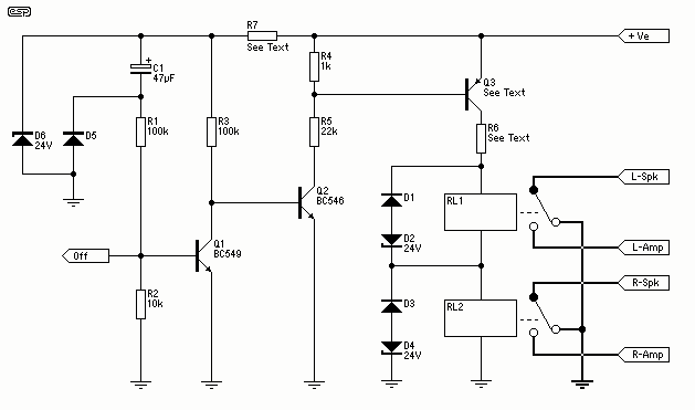
Loudspeaker Protection
The detector circuit shown in Figure 1 is simple and works well, and as shown will not trigger with a 30V RMS signal at 5Hz, but operates in 60ms with 30V DC applied, and in 50mS with a 45V DC...
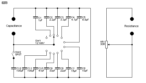
Loudspeaker Tester
Testing loudspeakers is covered in some detail in the passive crossover article, but it is irksome at best to have to fiddle about with clip leads and components lying all over the workbench. This simple project is intended to make...
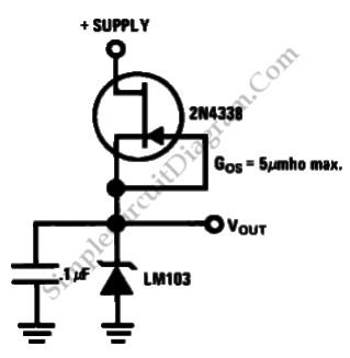
Low Power Regulator Reference
This is a simple circuit of a low-power voltage regulator reference. This circuit can produce a stable voltage reference.
The low-power voltage regulator reference circuit is designed to provide a consistent output voltage, which is crucial for various electronic applications requiring...
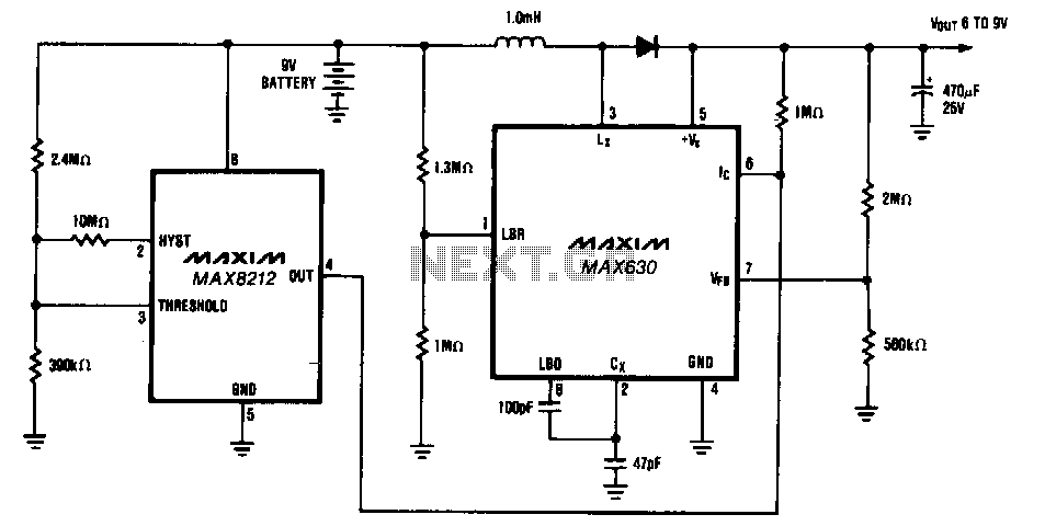
9-V-battery-life-extender
The circuit provides a minimum output of 7 V until the 9-V battery voltage drops below 2 V. When the battery voltage is above 7 V, the MAX630's IC pin is low, placing it in shutdown mode, which consumes only...
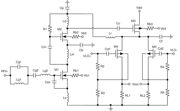
low power receiver serves multiple wireless standards
By combining a current-reuse amplifier and a switch-based mixer, a dual-band receiver front end offers excellent performance with extremely low power consumption.
The dual-band receiver front end integrates a current-reuse amplifier and a switch-based mixer to achieve high performance while maintaining...
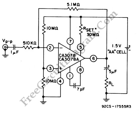
Single Cell Battery 1.5V 20dB Inverting Amplifier
This amplifier circuit exhibits a very low power consumption, with a total current draw of 675 nA. The output voltage swing is 300 mV peak-to-peak (pp) with a gain of 20.
The amplifier circuit is designed to operate with minimal power...
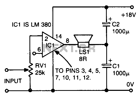
Novel loudspeaker coupling circuit
The ground side of the speaker is connected to the junction of two equal high-value capacitors (1000 µF is typical) across the supply. The amplifier output voltage will be Vs/2, and the voltage across CI (if CI and C2 are...
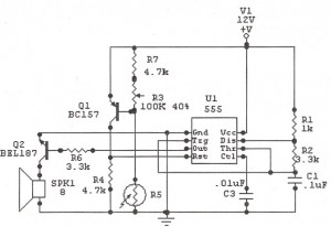
Light Alarm (Sun Up Alarm)
The IC 555 Light Alarm (Sun Up Alarm) circuit is designed to emit a loud alarm at dawn, particularly for individuals who struggle to wake up, even with a traditional alarm clock. The circuit is modifiable.
The IC 555 timer is...

micro power pulse generator
This circuit generates clean logic pulses with minimal current consumption. It is designed to produce short 2 ms pulses at a frequency of one pulse per second, drawing only 1 microamp from a 9-volt battery.
The described circuit operates efficiently by...