


Melody Doorbell circuit
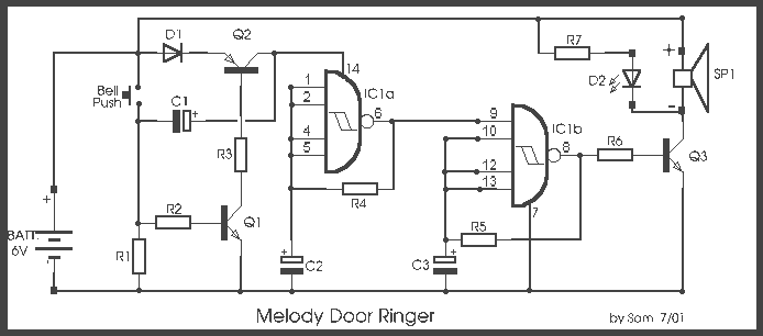
Description: In all the houses exist the bells in the door. All want, they have the possibility of being possible to change the intensity, the tone of sound. With this circuit we have this possibility. With the materials round the gates, we can change the sound. For the materials that exist in the circuit the frequencies are roughly 5 KHZ and 2 KHZ. The circuit functions only for small time interval afterwards the pressure of switch. Simultaneously with the sound we have also optical clue from LED D2. Changing the capacitors C2-C3, with different price of capacity, we create new sounds.
The described circuit functions as a customizable doorbell system, allowing users to modify sound intensity and tone. The circuit operates primarily through a combination of resistors, capacitors, and transistors, which work together to generate different audio frequencies, specifically around 5 kHz and 2 kHz.
The circuit's operation begins when a switch is pressed, providing a momentary power supply to the system. This action triggers a sound output through an 8-ohm speaker (SP), which is connected to the circuit's output stage. The sound produced can be altered by changing the values of capacitors C2 and C3; larger capacitance values will typically lower the frequency, while smaller values will raise it, thus creating a range of different tones.
The part list indicates the use of various components, including resistors (R1-R7), capacitors (C1-C3), diodes (D1), an LED (D2), and integrated circuits (IC1). The resistors are of 1/4W rating and include values such as 470 kΩ (R1), 22 kΩ (R2), and 3.9 kΩ (R3), among others, which are crucial for setting the current levels in the circuit. The transistors BC550 and BC560 (Q1-Q2) are used for switching and amplification purposes, ensuring that the output sound is both audible and adjustable.
The LED D2 serves as an optical indicator, illuminating when the circuit is active, providing a visual cue that complements the auditory signal. The power supply for this circuit can be derived from four 1.5V batteries in series, totaling 6V, or from an external 6V DC power source, ensuring versatility in power options.
In summary, this circuit design emphasizes user customization of doorbell sound characteristics while providing both auditory and visual feedback through its integrated components. The ability to alter capacitor values allows for a wide range of sound outputs, making it a practical solution for personalizing doorbell tones.In all the houses exist the bells in the door. All want, they have the possibility of being possible to change the intensity, the tone of sound. With this circuit we have this possibility. With the materials round the gates, we can change the sound. For the materials that exist in the circuit the frequencies are roughly 5 KHZ and 2 KHZ. The circuit functions only for small time interval afterwards the pressure of switch. Simultaneously with the sound we have also optical clue from LED D2. Changing the capacitors C2-C3, with different price of capacity, we create new sounds. Part List R1=470Kohm C1=22uF 25V Q1-3= BC 550 R2=22Kohm C2=470uF 25V Q2= BC 560 R3=3.9Kohm C3=1 uF 25V BATT=4X1,5V or external pack 6Vdc R4-5=330 ohm D1=1N4001 SP= Speaker 8R /0,5W R6=2.2Kohm D2=LED RED 3mm R7=1.2Kohm IC1=7413 All Resistors is 1/4W 5%
The described circuit functions as a customizable doorbell system, allowing users to modify sound intensity and tone. The circuit operates primarily through a combination of resistors, capacitors, and transistors, which work together to generate different audio frequencies, specifically around 5 kHz and 2 kHz.
The circuit's operation begins when a switch is pressed, providing a momentary power supply to the system. This action triggers a sound output through an 8-ohm speaker (SP), which is connected to the circuit's output stage. The sound produced can be altered by changing the values of capacitors C2 and C3; larger capacitance values will typically lower the frequency, while smaller values will raise it, thus creating a range of different tones.
The part list indicates the use of various components, including resistors (R1-R7), capacitors (C1-C3), diodes (D1), an LED (D2), and integrated circuits (IC1). The resistors are of 1/4W rating and include values such as 470 kΩ (R1), 22 kΩ (R2), and 3.9 kΩ (R3), among others, which are crucial for setting the current levels in the circuit. The transistors BC550 and BC560 (Q1-Q2) are used for switching and amplification purposes, ensuring that the output sound is both audible and adjustable.
The LED D2 serves as an optical indicator, illuminating when the circuit is active, providing a visual cue that complements the auditory signal. The power supply for this circuit can be derived from four 1.5V batteries in series, totaling 6V, or from an external 6V DC power source, ensuring versatility in power options.
In summary, this circuit design emphasizes user customization of doorbell sound characteristics while providing both auditory and visual feedback through its integrated components. The ability to alter capacitor values allows for a wide range of sound outputs, making it a practical solution for personalizing doorbell tones.In all the houses exist the bells in the door. All want, they have the possibility of being possible to change the intensity, the tone of sound. With this circuit we have this possibility. With the materials round the gates, we can change the sound. For the materials that exist in the circuit the frequencies are roughly 5 KHZ and 2 KHZ. The circuit functions only for small time interval afterwards the pressure of switch. Simultaneously with the sound we have also optical clue from LED D2. Changing the capacitors C2-C3, with different price of capacity, we create new sounds. Part List R1=470Kohm C1=22uF 25V Q1-3= BC 550 R2=22Kohm C2=470uF 25V Q2= BC 560 R3=3.9Kohm C3=1 uF 25V BATT=4X1,5V or external pack 6Vdc R4-5=330 ohm D1=1N4001 SP= Speaker 8R /0,5W R6=2.2Kohm D2=LED RED 3mm R7=1.2Kohm IC1=7413 All Resistors is 1/4W 5%
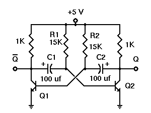
How does LED Flashes One by One in my Project Some Queries
A project called LED Flasher that sequentially flashes LEDs one by one. There is a query regarding the project, and any simple explanation would be greatly appreciated. A reference image or a link can be used for additional context.
The LED...
Doorbell Cascade
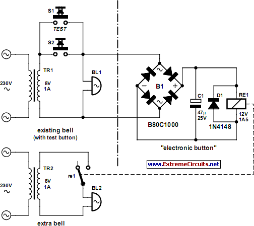
In certain situations, it may be necessary to adopt a more complex approach, even when simpler alternatives exist. This applies in the current scenario, where the objective is to install a second doorbell.
To implement the addition of a second doorbell,...
The simple LED Flasher by IC 4011
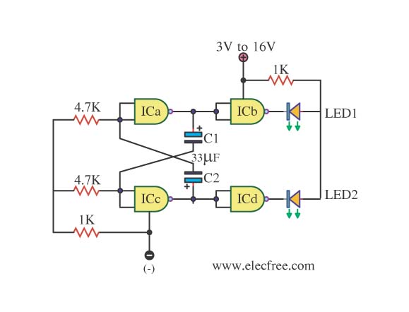
This is simply a LED flasher circuit that is suggested for construction. However, it is important to understand the use of transistors, which can be challenging when learning about digital electronics.
The LED flasher circuit operates by utilizing a basic astable...
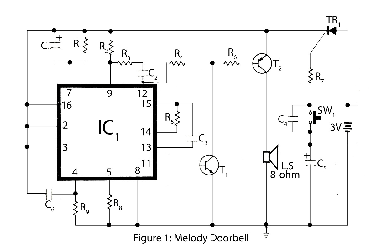
Advanced Melody Doorbell
The Advanced Melody doorbell is an intriguing project within the series of alarm circuit diagrams. It features a melody doorbell that operates using a battery instead of AC mains power.
The Advanced Melody doorbell circuit is designed to provide a unique...
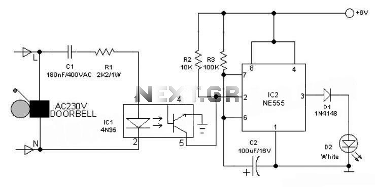
Electronic Doorbell Light Schematic
This 6V battery-operated doorbell light circuit can be connected in parallel with any existing AC 230V doorbell. When the doorbell switch is pressed, the bell sounds as usual, and the AC mains supply available across the doorbell is routed to...
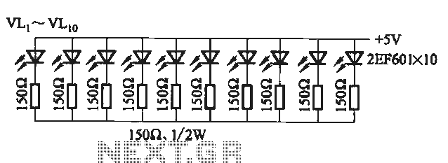
Flicker frequency of multiple sets of different light-emitting diode lights chain circuit
The circuit utilizes a 555 timer configured as a multivibrator, where the oscillation frequency is determined by resistors R1, R2, and capacitor C1. The frequency formula is given by fo = 1.443 / ((R1 + R2) * C1). The output...
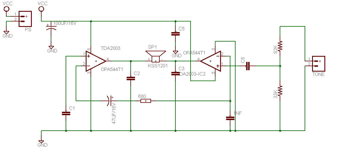
Base Treble Tone Control Circuit
This is a design for a tone control circuit. The circuit features the LM1036, which is a DC-controlled tone (bass/treble), volume, and balance circuit suitable for stereo applications in car radios, televisions, and audio systems.
The LM1036 integrated circuit is specifically...
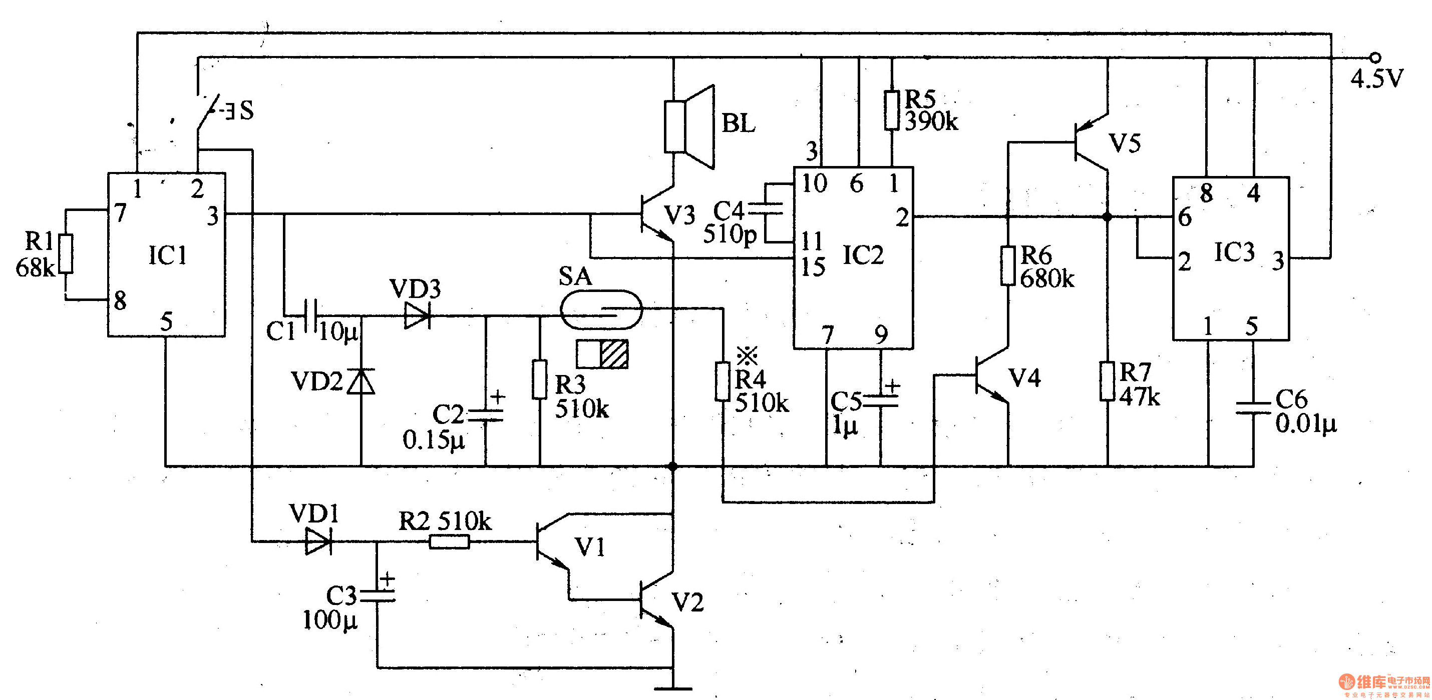
Politely welcoming electronic doorbell
The electronic doorbell circuit is designed to provide a polite and welcoming sound upon activation. It consists of several key components, including a trigger control circuit, an audio amplifier output circuit, a music circuit, and a voice delay control circuit,...
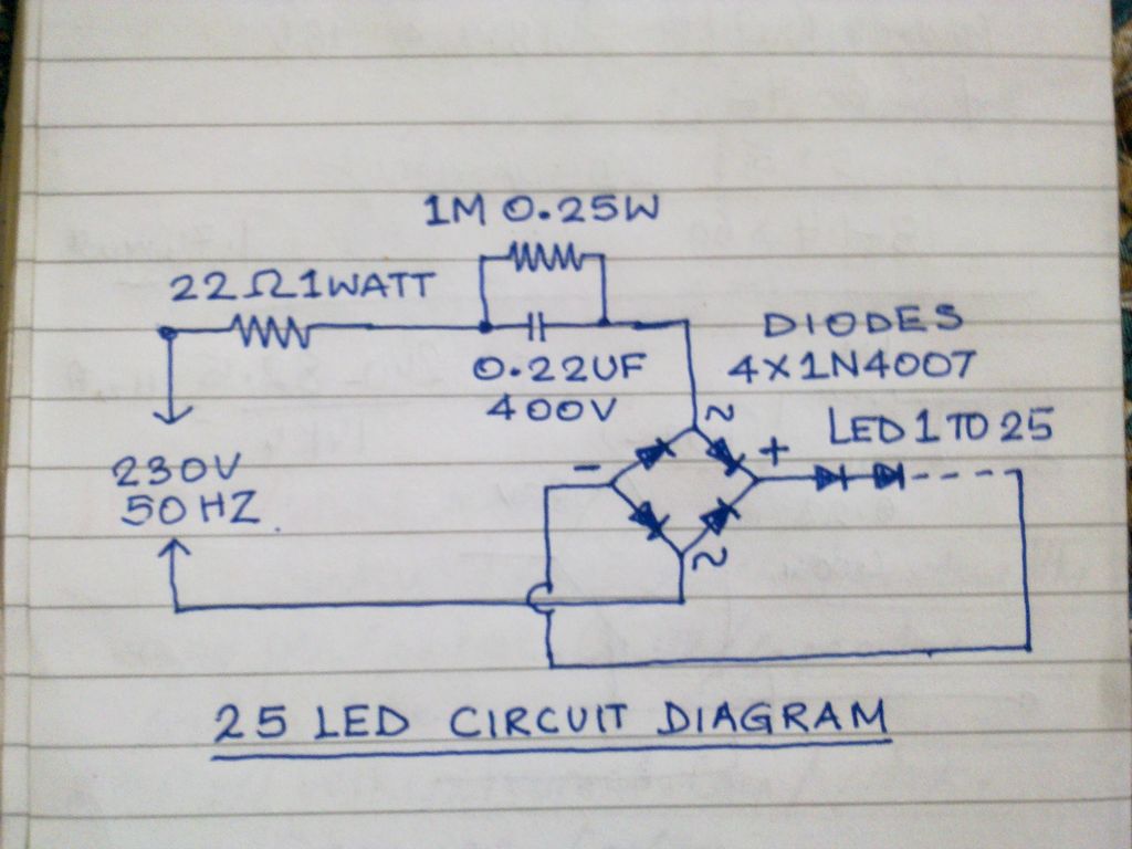
Mains operated led Lamp
This circuit operates 25 LEDs powered by a mains supply of 230V. A fluorescent lamp adapter was acquired from a scrap dealer for ease of disassembly.
The circuit consists of a series of 25 light-emitting diodes (LEDs) arranged to operate from...