


Model 300 Receiver
#phono preamp
#infrasonic filter
#buffer circuit
#low noise transistors
#receiver
#audio signal
#impedance
#cartridge
#audio equipment
#vintage audio
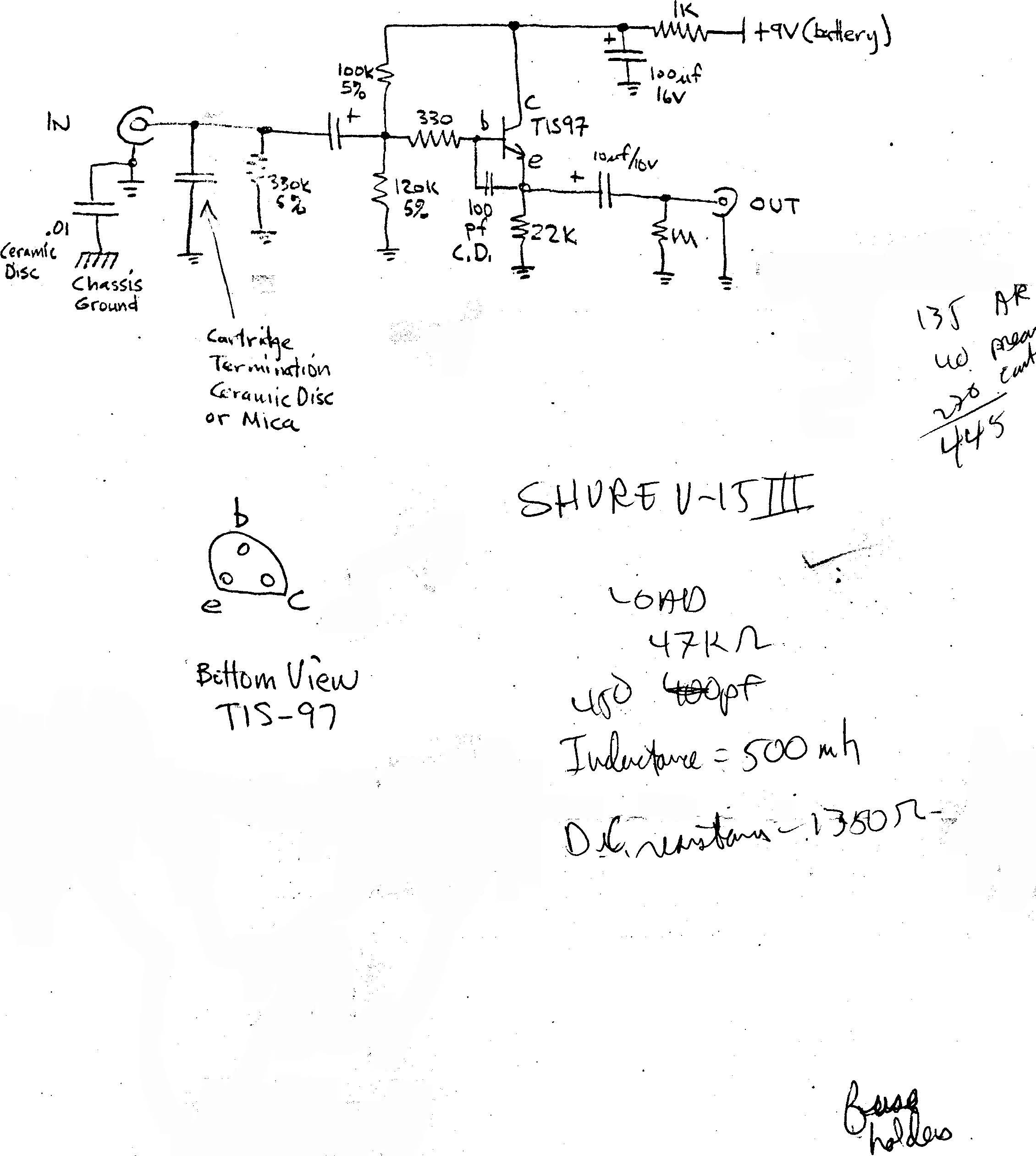
Description: The infrasonic filter was a particularly useful feature of the phono preamp. Instructions were provided on how to build an external buffer circuit to use with any phono preamp, in order to avoid cartridge impedance interaction. A letter was sent out with the circuit, and a pair of low noise transistors was included for free. Efforts were made to recreate some of the original model 300 materials from photocopies using Quark Express and a digital camera.
The infrasonic filter incorporated within the phono preamplifier serves to eliminate unwanted low-frequency noise that can interfere with audio playback. This feature is particularly beneficial in maintaining the integrity of the audio signal, ensuring that only the desired frequencies are amplified. The external buffer circuit is designed to mitigate issues related to cartridge impedance interaction, which can adversely affect sound quality. By isolating the cartridge from the preamp's input stage, the buffer circuit ensures a consistent impedance level, allowing for optimal signal transfer and fidelity.
The construction of the external buffer circuit requires careful selection of components, including low noise transistors, which are essential for minimizing signal distortion and maintaining low noise levels. The inclusion of these components, provided at no additional cost, highlights the commitment to enhancing audio performance.
To implement the buffer circuit, a basic schematic would typically include the transistors configured in a common emitter or common source arrangement, depending on the specific design requirements. Additional passive components such as resistors and capacitors would be utilized to set the biasing conditions and filter unwanted frequencies.
In terms of recreating the original model 300 materials, the use of software like Quark Express for layout design, alongside digital photography, allows for high-quality reproductions of the original documentation. This process ensures that the instructional materials remain accessible and informative for those looking to replicate or understand the design of the phono preamp and its associated circuitry.The infrasonic filter was a particularly useful feature of the phono preamp. He also offered instructions on how to build an external buffer circuit to use with any phono preamp, to avoid cartridge impedance interaction. He sent out a letter with the circuit, and even included a pair of low noise transistors - for free! As I did for the Advent Speaker ads, I`ve tried to recreate some of the original model 300 materials from photocopies using Quark Express and my digital camera.
The infrasonic filter incorporated within the phono preamplifier serves to eliminate unwanted low-frequency noise that can interfere with audio playback. This feature is particularly beneficial in maintaining the integrity of the audio signal, ensuring that only the desired frequencies are amplified. The external buffer circuit is designed to mitigate issues related to cartridge impedance interaction, which can adversely affect sound quality. By isolating the cartridge from the preamp's input stage, the buffer circuit ensures a consistent impedance level, allowing for optimal signal transfer and fidelity.
The construction of the external buffer circuit requires careful selection of components, including low noise transistors, which are essential for minimizing signal distortion and maintaining low noise levels. The inclusion of these components, provided at no additional cost, highlights the commitment to enhancing audio performance.
To implement the buffer circuit, a basic schematic would typically include the transistors configured in a common emitter or common source arrangement, depending on the specific design requirements. Additional passive components such as resistors and capacitors would be utilized to set the biasing conditions and filter unwanted frequencies.
In terms of recreating the original model 300 materials, the use of software like Quark Express for layout design, alongside digital photography, allows for high-quality reproductions of the original documentation. This process ensures that the instructional materials remain accessible and informative for those looking to replicate or understand the design of the phono preamp and its associated circuitry.The infrasonic filter was a particularly useful feature of the phono preamp. He also offered instructions on how to build an external buffer circuit to use with any phono preamp, to avoid cartridge impedance interaction. He sent out a letter with the circuit, and even included a pair of low noise transistors - for free! As I did for the Advent Speaker ads, I`ve tried to recreate some of the original model 300 materials from photocopies using Quark Express and my digital camera.
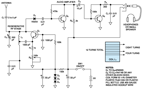
Simple receiver with microvolt sensitivity
The three-transistor circuit costs less than $10 to build, uses commonly available components, and consumes less than 10 mA from a single 9V battery. By winding coil L1 as shown, the circuit can receive signals in the 5 to 15...
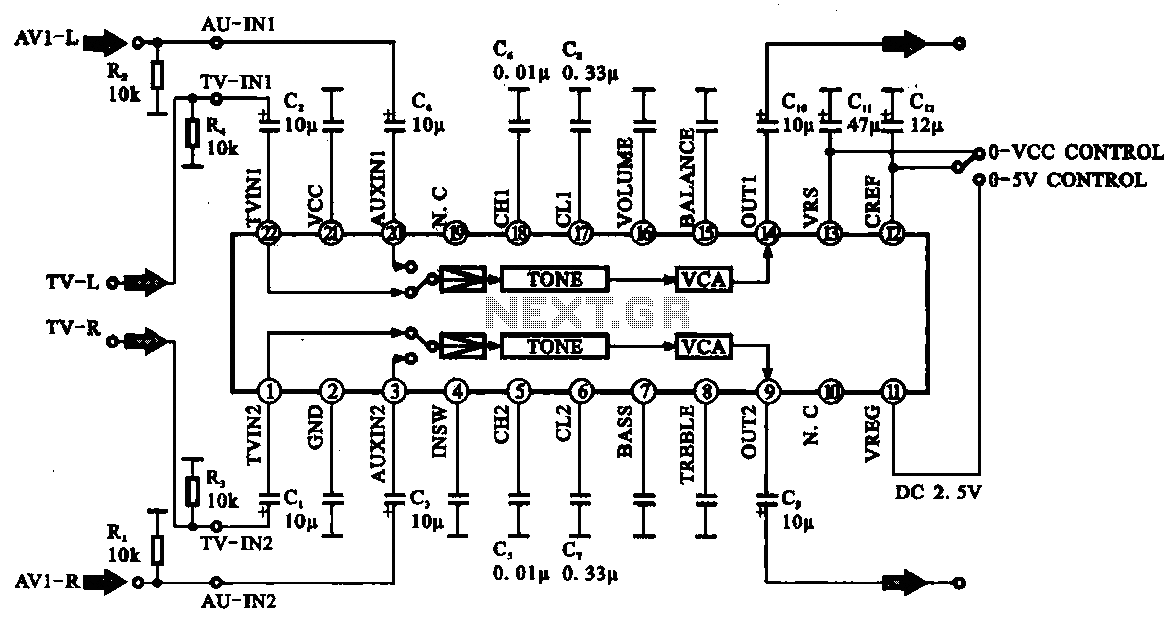
Audio signal control circuit
Audio signal control circuit. It illustrates a typical audio signal control circuit where two audio signals enter the integrated circuit through switching and tone controls (treble and bass), subsequently adjusting the output sent to the audio power amplifier.
The audio signal...
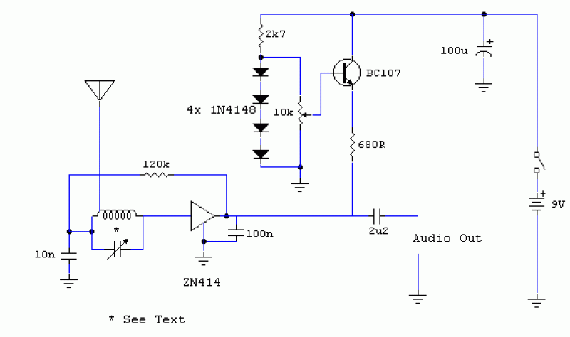
MK414 SW Receiver
The original data sheet for the MK414 indicates that the maximum working frequency is approximately 4 MHz. SW transmissions are sufficiently strong that this receiver can effectively operate with signals up to about 6 or 7 MHz. A 10k resistor...
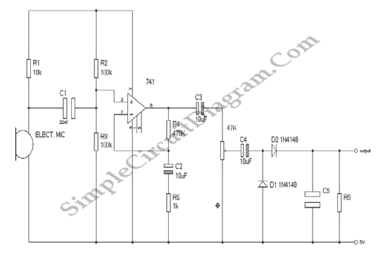
Audio Signal Strength Detector/Converter
Below is the schematic diagram of an audio input module. This module is capable of producing a DC output voltage that is proportional to the amplitude of the input signal.
The audio input module typically consists of several key components that...
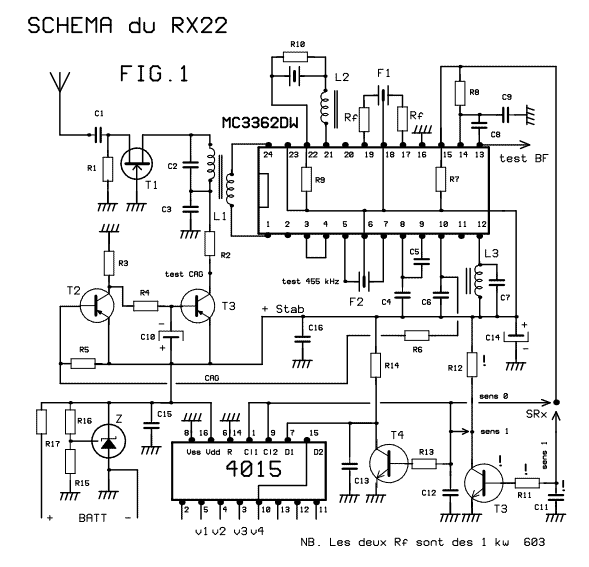
41-72MHz micro-receiver ( MC3362 )
This receiver weighs about 6 g, used in 41 and 72 MHz, met a great success with readers of the magazine. The RX22 is the subject of these lines is improved RX20. Adding a preamp-HF improving sensitivity. Establishment of an...
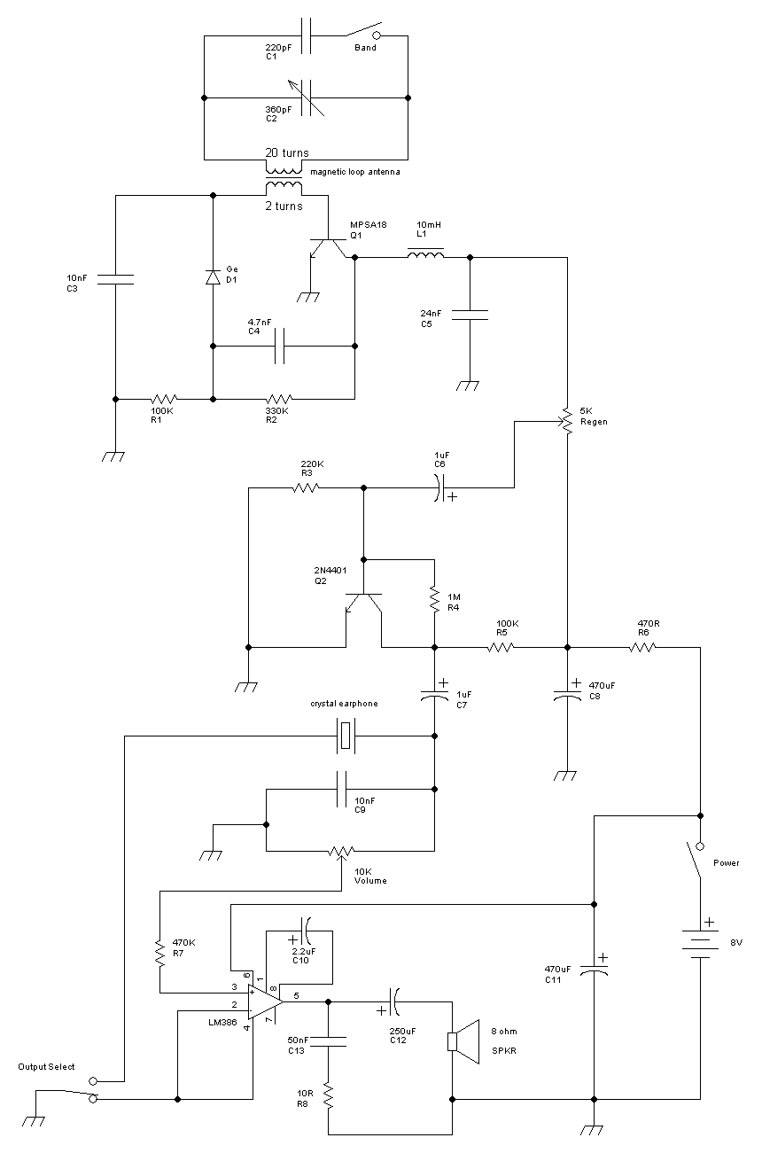
Radio circuits built
This receiver is a modification of Charles Wenzel's Two Transistor Reflex Radio. Instead of a ferrite AM loopstick antenna, a magnetic loop antenna is used, and an LM386 amplifier stage has been added to drive an 8-ohm speaker. A switch...

DIY phono preamp project
What is the likely cost of the Aleph Ono, specifically regarding the parts? Is it similar to the Pearl but improved?
The Aleph Ono is a high-fidelity phono stage designed to deliver exceptional audio performance. When estimating the cost of the...
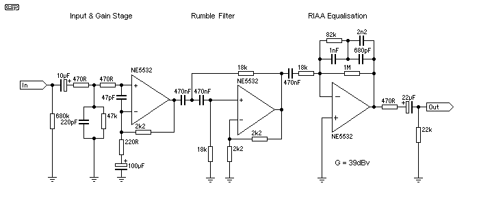
Phono Preamps For All
Cleaned Input: This is a collection of phono (black vinyl for the youngsters) preamps and equalisation circuits, one of which is sure to meet your requirements. These are not my circuits, but were contributed by a reader, so I am...
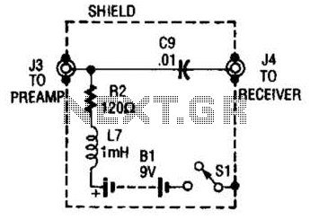
Receiver-Interface Circuit For Preamps Circuit
The purpose of the receiver/interface circuit is to pass RF to the receiver through capacitor C9, while adding DC power to the feedline through resistor R2 and RF choke L7.
The receiver/interface circuit is designed to facilitate the transmission of radio...