


One instance of loudness control circuit
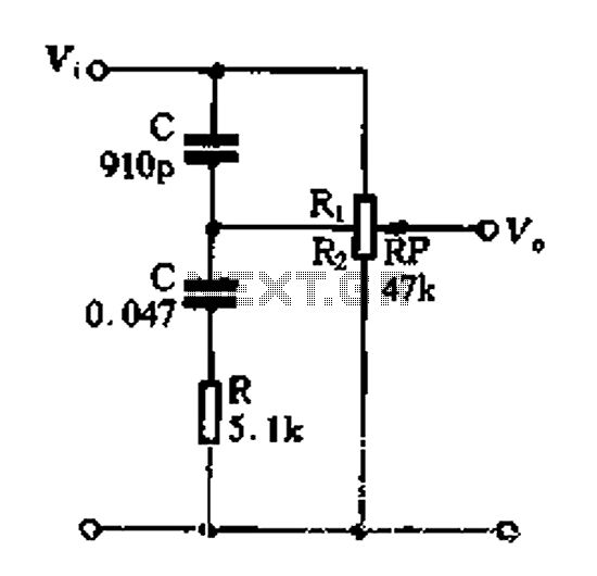
Description: Figure 1-89 illustrates a loudness control circuit. A potentiometer is connected to ground, with 30% of the total resistance at the tap. When the slider arm is adjusted to the tap position, a midrange attenuation of 30 dB is observed, with a bass attenuation of approximately 23 dB at 100 Hz (indicating a relative enhancement of 7 dB) and a treble attenuation of around 27 dB at 10 kHz (indicating a relative lift of 3 dB).
The loudness control circuit depicted in Figure 1-89 employs a potentiometer to adjust audio frequency response dynamically. The configuration allows for a variable resistance that influences the signal levels across different frequency bands, providing a tailored listening experience. The potentiometer is designed to offer a 30% resistance tap to ground, effectively creating a voltage divider that alters the audio signal's amplitude.
When the slider arm of the potentiometer is moved to the specified tap position, it results in significant attenuation across the frequency spectrum. The midrange frequencies experience a notable attenuation of 30 dB, which can effectively reduce the prominence of vocals and instruments that typically occupy this range, thereby allowing for a more balanced sound profile.
For lower frequencies, specifically at 100 Hz, a bass attenuation of approximately 23 dB is achieved. This reduction can be interpreted as a relative enhancement of 7 dB, meaning that the overall sound may be perceived as bass-heavy when compared to the original signal. This feature can be particularly useful in environments where low-frequency response is overwhelming or in need of adjustment.
In the higher frequency range, specifically at 10 kHz, the circuit provides an attenuation of about 27 dB, corresponding to a relative lift of 3 dB. This adjustment allows for fine-tuning of treble frequencies, which can be beneficial in reducing harshness or sibilance in audio playback.
Overall, this loudness control circuit is designed to enhance user experience by allowing for customized adjustments to the audio output, catering to personal preferences and varying listening environments. The careful calibration of frequency attenuation ensures a well-rounded sound profile that can adapt to different acoustic conditions.Figure 1-89 is an example of loudness control circuit. Potentiometer from the ground 30% of the total resistance at the tap. When the slide arm when screwed to the tap position , found midrange attenuation 30dB, 100Hz bass attenuation of approximately 23dB (ie, relative to enhance 7dB), treble lOkHz attenuation of about 27dB (ie, the relative lift 3).
The loudness control circuit depicted in Figure 1-89 employs a potentiometer to adjust audio frequency response dynamically. The configuration allows for a variable resistance that influences the signal levels across different frequency bands, providing a tailored listening experience. The potentiometer is designed to offer a 30% resistance tap to ground, effectively creating a voltage divider that alters the audio signal's amplitude.
When the slider arm of the potentiometer is moved to the specified tap position, it results in significant attenuation across the frequency spectrum. The midrange frequencies experience a notable attenuation of 30 dB, which can effectively reduce the prominence of vocals and instruments that typically occupy this range, thereby allowing for a more balanced sound profile.
For lower frequencies, specifically at 100 Hz, a bass attenuation of approximately 23 dB is achieved. This reduction can be interpreted as a relative enhancement of 7 dB, meaning that the overall sound may be perceived as bass-heavy when compared to the original signal. This feature can be particularly useful in environments where low-frequency response is overwhelming or in need of adjustment.
In the higher frequency range, specifically at 10 kHz, the circuit provides an attenuation of about 27 dB, corresponding to a relative lift of 3 dB. This adjustment allows for fine-tuning of treble frequencies, which can be beneficial in reducing harshness or sibilance in audio playback.
Overall, this loudness control circuit is designed to enhance user experience by allowing for customized adjustments to the audio output, catering to personal preferences and varying listening environments. The careful calibration of frequency attenuation ensures a well-rounded sound profile that can adapt to different acoustic conditions.Figure 1-89 is an example of loudness control circuit. Potentiometer from the ground 30% of the total resistance at the tap. When the slide arm when screwed to the tap position , found midrange attenuation 30dB, 100Hz bass attenuation of approximately 23dB (ie, relative to enhance 7dB), treble lOkHz attenuation of about 27dB (ie, the relative lift 3).
Potentiometric voltmeter
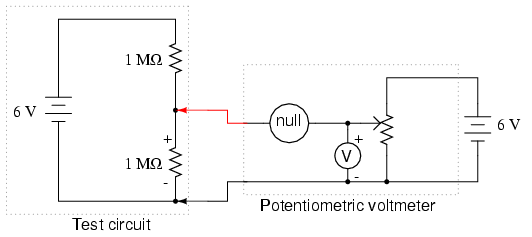
The potentiometer value is not critical; any value from 1 kΩ to 100 kΩ is acceptable. If the "precision potentiometer" described earlier in this chapter has been constructed, it is recommended for use in this experiment. The actual values of...
Using tap potentiometer loudness circuit
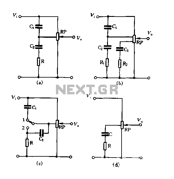
Figure 1.88 illustrates the loudness control circuit utilizing multiple taps on a potentiometer. In Figure (A), the connection is made between the tap and the potentiometer's input, along with the ground. An RC compensation network is employed, where the slide...
AVC Automatic Volume Control Circuit
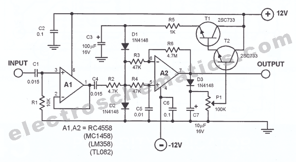
AVC - The circuit regulates the volume line automatically, providing an output voltage of approximately 4 volts peak to peak. This voltage remains consistent.
The Automatic Volume Control (AVC) circuit is designed to manage audio levels dynamically, ensuring a stable output...
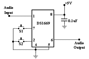
digital volume control
This circuit allows for amplifier volume control without the need for a potentiometer, utilizing an IC DS1669. The operating voltage for this type of IC ranges from 4.5 volts to 8 volts; however, in this circuit, it is used at...
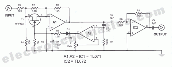
AVC Automatic Volume Control Circuit
The function of this automatic volume control circuit is to amplify signals without distorting their dynamic compression. The amplitude differences in the signal are leveled off, eliminating disturbing effects. This technique avoids overcompensation in volume. The circuit is utilized to...
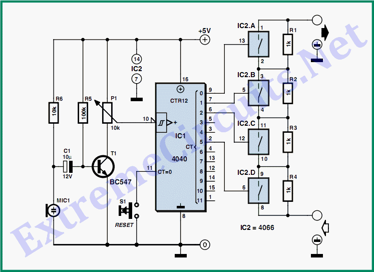
Stepped Volume Control
This circuit can amplify music, sirens, or speech in response to increased ambient noise levels. It provides a solution for enabling a robot to effectively communicate in noisy environments.
This circuit utilizes a sound detection mechanism to monitor ambient noise levels....
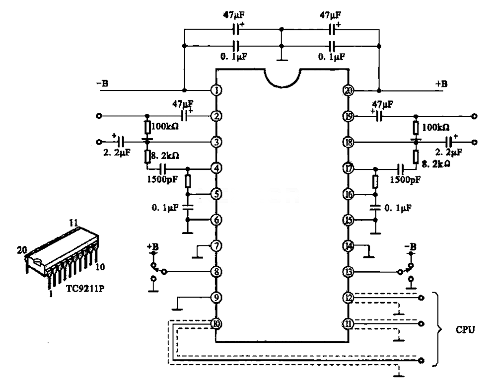
A typical electronic volume control circuit
A typical electronic volume control circuit is commonly used in stereo audio devices connected through a computer (CPU). The circuit adjusts the volume of stereo signals via input and output pins. Control signals are sent to the CPU (including clock,...
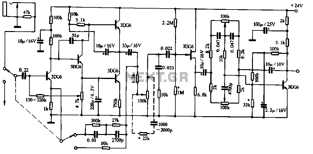
Practical loudness control circuit
Figure 1-91 illustrates a practical loudness volume control circuit designed for integration with a preamplifier and tone control system. This circuit is positioned behind the output capacitor load (OCL) and can be connected to the main amplifier. Its effectiveness has...
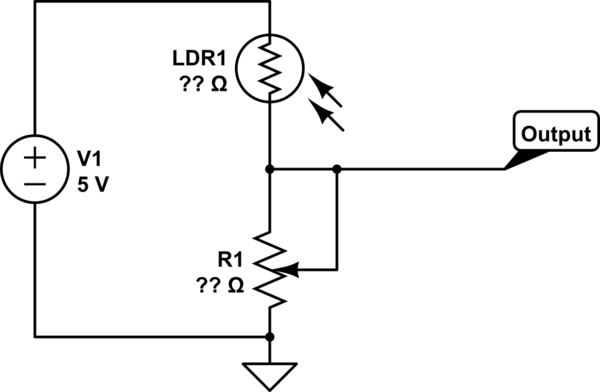
potentiometer Making an adjustable resistance
This part of the circuit is isolated from any other component, except for the 5V and ground connections. It includes LEDs and a shift register, which may not interact significantly. The LDR (Light Dependent Resistor) is utilized solely as a...