


Otari MX-5050 BII Problem - Not for the faint of heart!
#Otari MX-5050
#audio equipment
#diagnostic
#repair
#tape recorder
#vintage audio
#electronics repair
#audio troubleshooting
#BII model

Description: This is a diagnostic problem, and it is important to include as much information as possible for those involved.
In the context of electronic circuit diagnostics, a systematic approach is essential for identifying and resolving issues. The diagnostic process typically involves several key steps:
1. **Problem Definition**: Clearly define the symptoms observed in the circuit. This may include unexpected behavior, failure to operate, or performance below specifications.
2. **Information Gathering**: Collect all relevant data, including circuit schematics, component specifications, and operational conditions. This information is vital for understanding the context of the problem.
3. **Visual Inspection**: Conduct a thorough visual examination of the circuit board and components. Look for signs of damage such as burnt components, broken traces, or soldering issues.
4. **Testing Procedures**: Utilize appropriate testing methods, such as multimeter measurements, oscilloscope observations, and signal tracing, to assess the functionality of individual components and sections of the circuit.
5. **Isolation of Faults**: Identify the faulty components or sections of the circuit by systematically isolating parts of the circuit and testing them independently. This may involve disconnecting certain sections and checking for proper operation.
6. **Component Replacement**: Once the faulty component is identified, replace it with a new part that meets the original specifications. Ensure proper handling and soldering techniques to avoid introducing new issues.
7. **Verification and Testing**: After repairs, re-test the circuit to ensure it operates as intended. This may involve running the circuit under normal conditions and verifying that all specifications are met.
8. **Documentation**: Record the findings, procedures followed, and any changes made to the circuit. This documentation can be invaluable for future reference and for others who may encounter similar issues.
By following these steps, a comprehensive diagnostic process can be established, leading to effective troubleshooting and resolution of electronic circuit problems.Hey guys, apologies in advance for the wall of text, but this is a diagnostic problem and I felt I should include as much info as possible for those..
In the context of electronic circuit diagnostics, a systematic approach is essential for identifying and resolving issues. The diagnostic process typically involves several key steps:
1. **Problem Definition**: Clearly define the symptoms observed in the circuit. This may include unexpected behavior, failure to operate, or performance below specifications.
2. **Information Gathering**: Collect all relevant data, including circuit schematics, component specifications, and operational conditions. This information is vital for understanding the context of the problem.
3. **Visual Inspection**: Conduct a thorough visual examination of the circuit board and components. Look for signs of damage such as burnt components, broken traces, or soldering issues.
4. **Testing Procedures**: Utilize appropriate testing methods, such as multimeter measurements, oscilloscope observations, and signal tracing, to assess the functionality of individual components and sections of the circuit.
5. **Isolation of Faults**: Identify the faulty components or sections of the circuit by systematically isolating parts of the circuit and testing them independently. This may involve disconnecting certain sections and checking for proper operation.
6. **Component Replacement**: Once the faulty component is identified, replace it with a new part that meets the original specifications. Ensure proper handling and soldering techniques to avoid introducing new issues.
7. **Verification and Testing**: After repairs, re-test the circuit to ensure it operates as intended. This may involve running the circuit under normal conditions and verifying that all specifications are met.
8. **Documentation**: Record the findings, procedures followed, and any changes made to the circuit. This documentation can be invaluable for future reference and for others who may encounter similar issues.
By following these steps, a comprehensive diagnostic process can be established, leading to effective troubleshooting and resolution of electronic circuit problems.Hey guys, apologies in advance for the wall of text, but this is a diagnostic problem and I felt I should include as much info as possible for those..
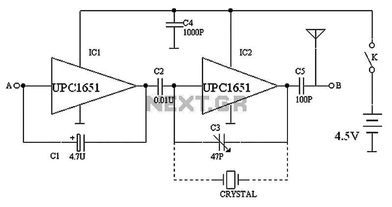
Multipurpose tape recorders TV signal generator circuit
The circuit depicted in the figure includes IC1 and C1, which form a low-frequency oscillator operating at approximately 400 Hz. IC2 and C3 are configured to create a frequency oscillator around 37 MHz. The low-frequency signal is output from C2,...

Conversation Recorder
This circuit enables automatic switching-on of the tape recorder when the handset is lifted. The tape recorder gets switched off when the handset is replaced. The signals are suitably attenuated to a level at which they can be recorded using...
Conversation Recorder
This circuit enables automatic switching-on of the tape recorder when the handset is lifted. The tape recorder gets switched off when the handset is replaced. The signals are suitably attenuated to a level at which they can be recorded using...
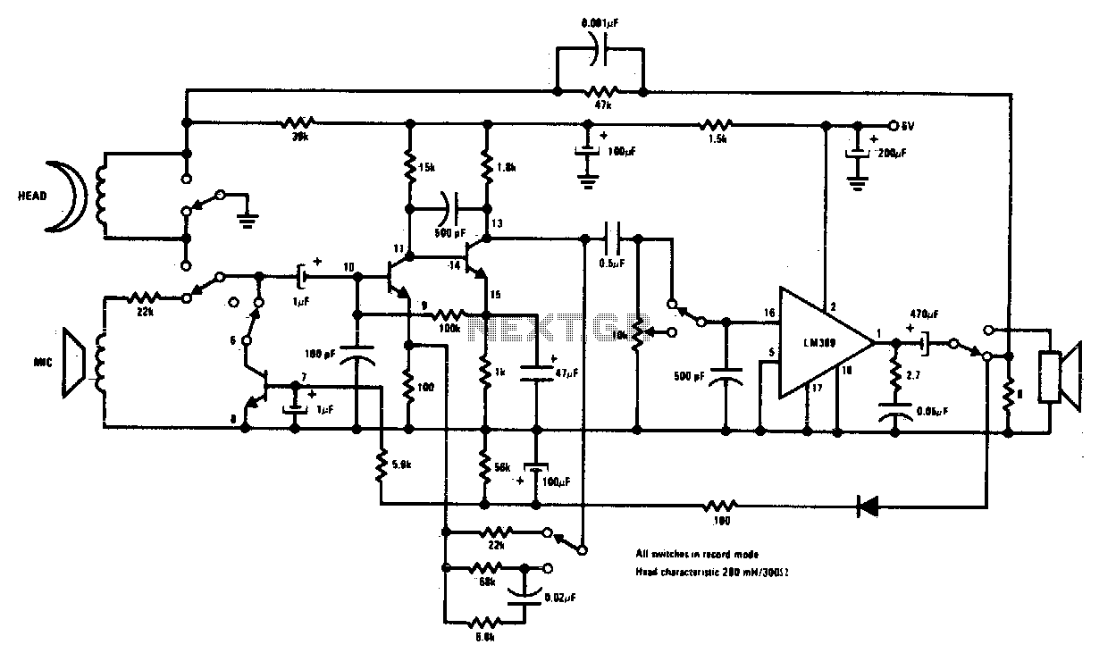
Tape recorder
Complete record/playback cassette tape machine amplifier. Two of the transistors act as signal amplifiers, with the third used for automatic level control during the record mode.
The cassette tape machine amplifier is designed to facilitate both recording and playback functionalities, ensuring...
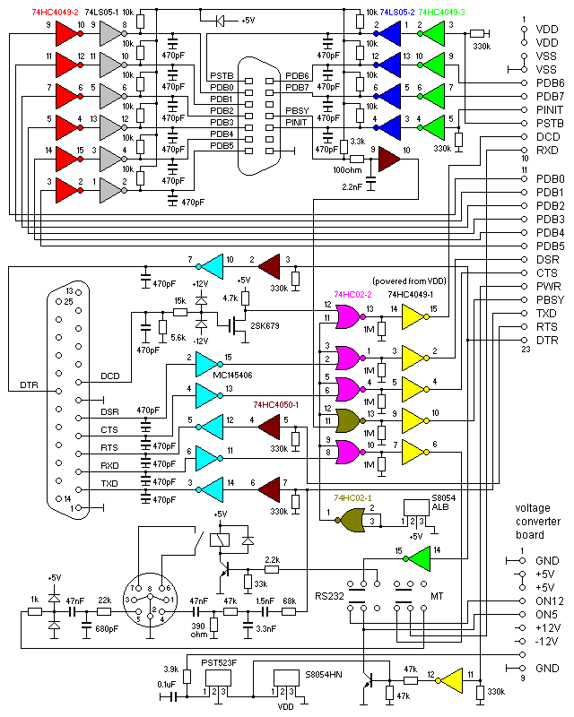
Pinout Of The Fa-6
Pinout of the FA-6 - posted in General Discussion: A user inquired about connecting a tape recorder with "line in," "line out," and "remote" features to the FA-6. The FA-6 is equipped with an 8-pin DIN connector, but the user...
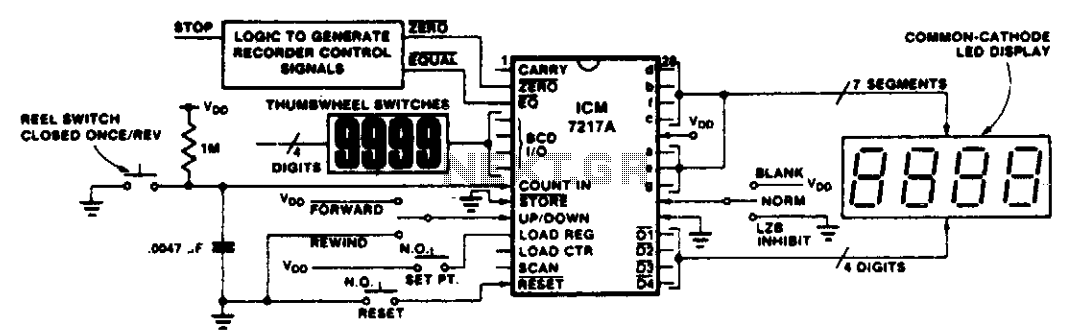
Tape recorder position indicator-controller
This circuit illustrates various applications of up/down counting for monitoring dimensional position. In the tape recorder application, the LOAD REGISTER, EQUAL, and ZERO outputs are utilized to control the recorder. To ensure the recorder stops at a specific point on...
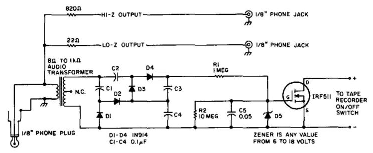
Audio-Powered Tape Recorder Controller
A tape recorder can be controlled by rectifying the audio input and driving an IRF511 power MOSFET to switch the tape recorder on when audio is present. This circuit was used with a communications receiver to record intermittent transmissions, such...
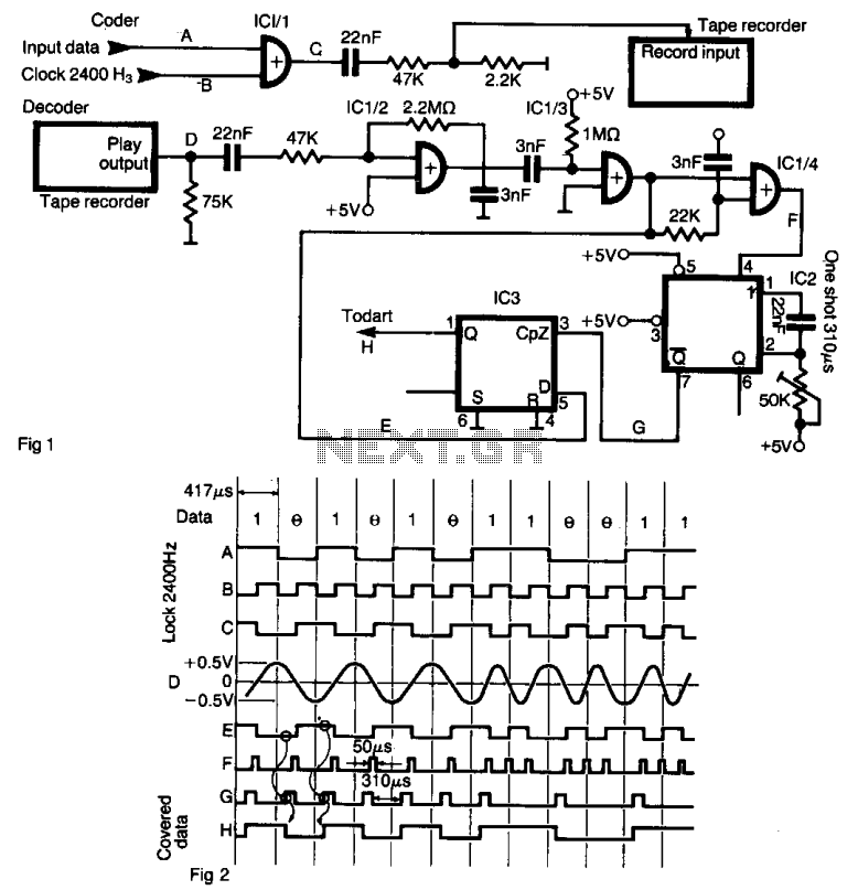
Tape recorder interface
The interface enables data to be recorded on a standard tape recorder at a speed of 2400 bits per second. The serial data stream is encoded with a clock frequency of 2400 Hz using an XOR gate (IC 1/1). The...
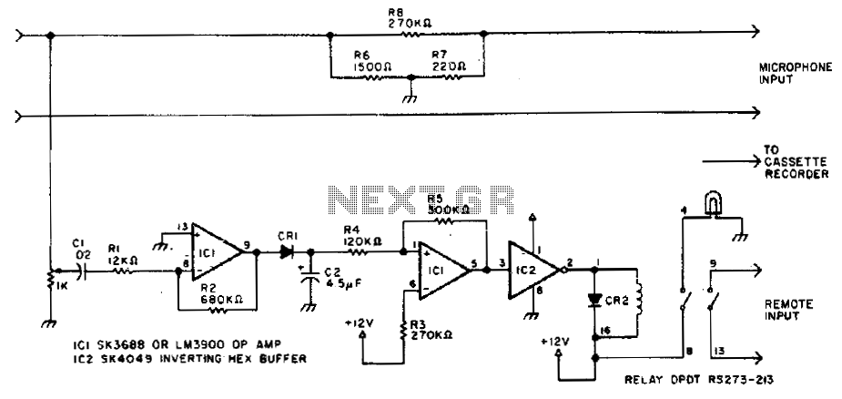
Automatic tape recording
Amateurs do not have to miss the action while away from the rig. This circuit activates a tape recorder whenever the receiver's squelch is broken. After signal loss, the recorder will turn off following a slight delay.
The described circuit serves...