


Overload speaker protection circuit
#speaker protection
#overload protection
#amplifier
#relay
#SCR
#audio signal
#circuit breaker
#transistor
#safety
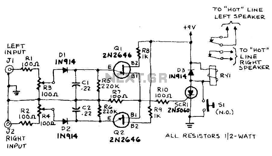
Description: The circuit input is derived from the terminal loudspeaker or amplifier output jacks. If the right channel signal is sufficiently strong to charge capacitor C1 to a potential that exceeds the breakdown voltage of the emitter of transistor Q1, a voltage pulse will be generated across resistor R7. Similarly, if the left channel signal is strong enough to charge capacitor C2 to a voltage exceeding the breakdown voltage of the emitter of transistor Q2, a pulse will also appear across R7. This pulse triggers the sensitive silicon-controlled rectifier (SCR) SCR1, which has a gate-trigger current (IGT) of less than 15 mA, causing it to enter a latched conducting state and activate relay RY1. The operation of the relay interrupts the speaker circuit, resulting in silence, which serves as an alert for the issue. To reset the circuit and restore normal operation, the amplifier volume should be reduced, followed by pressing and releasing switch S1. The circuit can be configured to activate at any power level between 15 watts RMS and 150 watts RMS. Calibration involves deliberately overdriving the signal at the input of the right speaker protection and adjusting potentiometer R3 until relay RY1 activates. The same procedure is applied to the left channel, with potentiometer R4 being adjusted accordingly. After calibration, the circuit is ready for use.
The circuit operates as a protective measure for audio amplifiers and loudspeakers, ensuring that excessive power levels do not damage the connected components. The use of capacitors C1 and C2 allows for the detection of potentially harmful signals from both the right and left audio channels. The voltage pulses generated by these capacitors when charged beyond their respective thresholds are crucial for activating the SCR, which serves as a reliable electronic switch.
Relay RY1 plays a pivotal role in this circuit. When triggered by the SCR, it opens the circuit to the loudspeakers, effectively silencing them and preventing any further damage from excessive power. The incorporation of a reset switch (S1) ensures user control over the system, allowing for a manual reset after an over-power condition has been detected.
Calibration is a critical step in the setup process, as it ensures that the circuit responds appropriately to the specific characteristics of the audio amplifier being used. By adjusting the potentiometers R3 and R4, users can fine-tune the sensitivity of the circuit to match the output capabilities of their amplifiers, providing flexibility for different systems. This feature enhances the circuit's usability across a range of audio equipment, making it a versatile solution for speaker protection.
Overall, this circuit design exemplifies a practical approach to safeguarding audio equipment, combining simple yet effective components to create a reliable protective mechanism against over-power conditions.The circuit input is taken from the terminal loudspeaker or amplifier output jacks. If the right channel is large enough to charge C1 to a potential which exceeds the breakdown voltage of the emitter of Ql, a voltage pulse appears in R7. Similarly, if the left channel signal is large enough to charge C2 to a voltage that is greater than the breakdown voltage of the emitter of Q2 ", a pulse appears in R7.
The pulse triggers in R7 5CRI. A door sensitive SCR (LGT less than 15 RNA or IGT is the gate-trigger current) that locks in a conducting state and energizes Ryl. The action of the relay will interrupt the speaker circuit. and silence follows you must alert on the problem. Reduce the volume on your amplifier, then press and release 51 to reset the circuit and restore normal operation. The circuit can be set to go off at any level of 15 watts RMS to 150. To calibrate . deliberately over-power signal at the entrance of the right speaker protection and adjust R3 until RY1 boosts.
Do the same with the left channel, this time adjusting R4. The circuit is now calibrated and ready employment.
The circuit operates as a protective measure for audio amplifiers and loudspeakers, ensuring that excessive power levels do not damage the connected components. The use of capacitors C1 and C2 allows for the detection of potentially harmful signals from both the right and left audio channels. The voltage pulses generated by these capacitors when charged beyond their respective thresholds are crucial for activating the SCR, which serves as a reliable electronic switch.
Relay RY1 plays a pivotal role in this circuit. When triggered by the SCR, it opens the circuit to the loudspeakers, effectively silencing them and preventing any further damage from excessive power. The incorporation of a reset switch (S1) ensures user control over the system, allowing for a manual reset after an over-power condition has been detected.
Calibration is a critical step in the setup process, as it ensures that the circuit responds appropriately to the specific characteristics of the audio amplifier being used. By adjusting the potentiometers R3 and R4, users can fine-tune the sensitivity of the circuit to match the output capabilities of their amplifiers, providing flexibility for different systems. This feature enhances the circuit's usability across a range of audio equipment, making it a versatile solution for speaker protection.
Overall, this circuit design exemplifies a practical approach to safeguarding audio equipment, combining simple yet effective components to create a reliable protective mechanism against over-power conditions.The circuit input is taken from the terminal loudspeaker or amplifier output jacks. If the right channel is large enough to charge C1 to a potential which exceeds the breakdown voltage of the emitter of Ql, a voltage pulse appears in R7. Similarly, if the left channel signal is large enough to charge C2 to a voltage that is greater than the breakdown voltage of the emitter of Q2 ", a pulse appears in R7.
The pulse triggers in R7 5CRI. A door sensitive SCR (LGT less than 15 RNA or IGT is the gate-trigger current) that locks in a conducting state and energizes Ryl. The action of the relay will interrupt the speaker circuit. and silence follows you must alert on the problem. Reduce the volume on your amplifier, then press and release 51 to reset the circuit and restore normal operation. The circuit can be set to go off at any level of 15 watts RMS to 150. To calibrate . deliberately over-power signal at the entrance of the right speaker protection and adjust R3 until RY1 boosts.
Do the same with the left channel, this time adjusting R4. The circuit is now calibrated and ready employment.
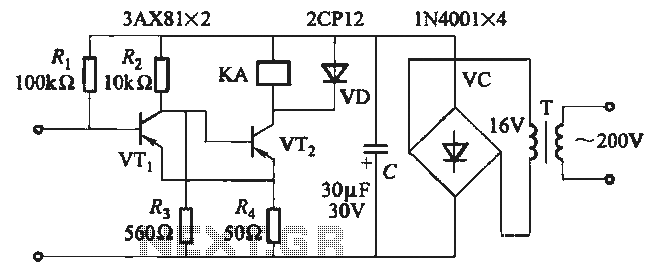
JB-22 transistor relay circuit
When the input is disconnected, the transistor VTi conducts, while VTz is in cutoff, causing relay KA to release. When the input is shorted, VTi is cut off, VTz conducts, and relay KA is activated.
In this circuit configuration, the operation...
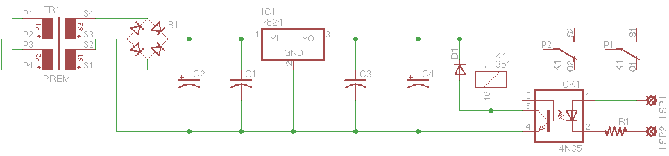
Isolated 24V Relay Controller
This is a common control voltage in industrial and telecommunications equipment, making relays frequently found in surplus equipment. Many relays can operate effectively on both AC and DC, providing a straightforward solution when the control voltage is switched mechanically, such...
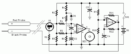
Quick On-Board Junction TesterCircuit
Acoustic check of transistor and diode junctions. Also suitable as a continuity tester. Short circuits or broken PCB tracks can be easily recognized.
The acoustic check of transistor and diode junctions is a method used to assess the functionality of these...
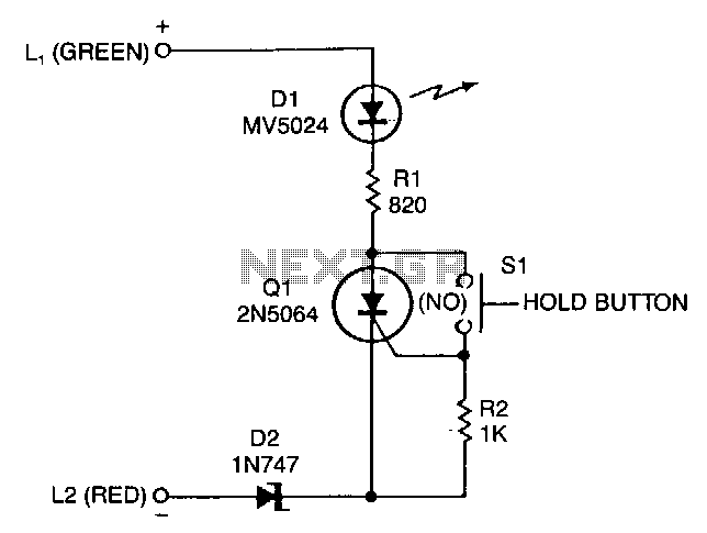
Add-on-telephone-hold-button
A sensitive-gate SCR provides a line-holding current of 20 to 40 mA, depending on loop resistance. It also lights an LED to give the user a positive indication that the telephone line is on hold. The 20 to 40 mA...

Transistor Amplifier Circuit with Diagram for 12 Watts
A simple transistor amplifier circuit diagram and schematic that can be used as a 12-watt audio transistor amplifier. An operational amplifier (op-amp) integrated circuit (IC) is used to produce the required gain.
This circuit is designed to amplify audio signals, making...
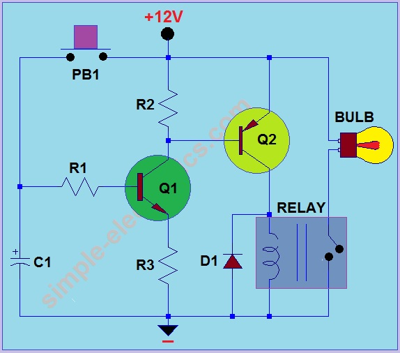
Car Headlight with Delay Circuit
This circuit operates by activating a headlight when the push-button PB1 is pressed. The headlight remains illuminated for a predetermined duration, which can range from several seconds to minutes, before automatically turning off. When PB1 is engaged, capacitor C1 begins...
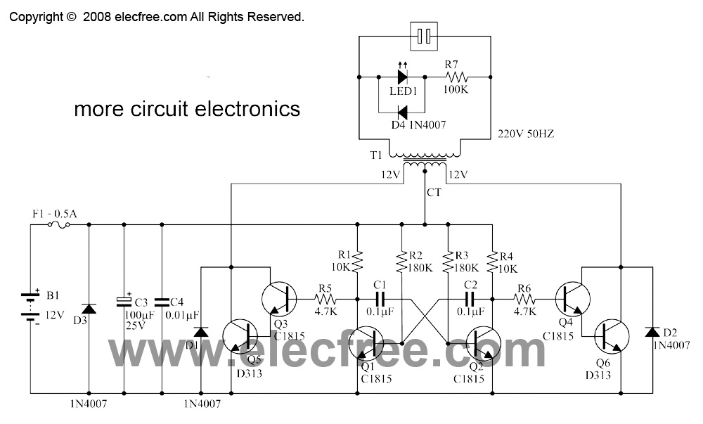
mini inverter 10w 30w by transistor d313
This is a small inverter rated at 30 watts. It converts DC voltage from a 12V battery to AC voltage of 220V-230V at a frequency of 50Hz, which is the same electricity used in households. It can power 2-3 air...
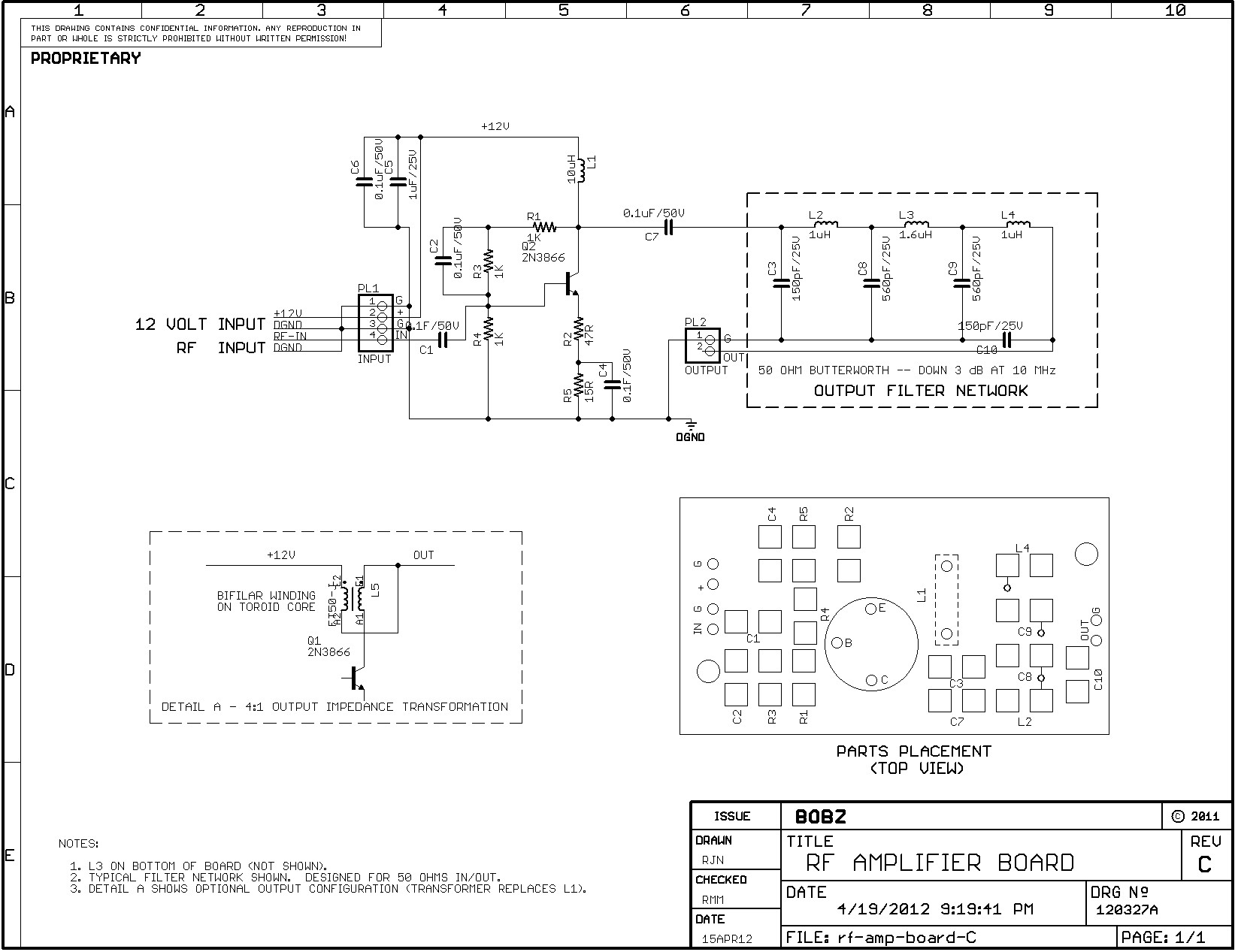
RF-AMP Documentation
The amplifier is suitable for various projects to buffer and amplify outputs from devices such as Direct Digital Synthesizer (DDS) chips. It was initially designed to amplify the output of the 9833 DDS chip and is also intended for Amateur...
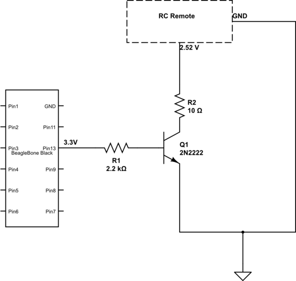
microcontroller Why this transistor logic as switch is not working
The remote control of an RC car was modified by extending wires from the backward, forward, left, and right switches. Grounding any of these wires completes the circuit and sends a signal to the car. The intention is to close...