


phone ringtone generator circuit
#piezo-buzzer
#oscillator
#transistor
#IC
#ringtone
#tone generator
#pulse
#frequency
#sound
#electronics
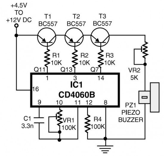
Description: The circuit generates pulses of 1.25 Hz from pin 1 and 20 Hz from pin 14. The three output pins of IC1 are connected to the base terminals of transistors T1, T2, and T3 through resistors R1, R2, and R3, respectively. A built-in oscillator-type piezo buzzer produces a tone of approximately 1 kHz. In this circuit, the piezo buzzer is activated and deactivated at a frequency of 20 Hz by transistor T3. The collector of transistor T3 outputs 20 Hz pulses for a duration of 0.4 seconds. After this interval, the 20 Hz pulses are generated again for another 0.4 seconds, followed by a two-second silent interval. This pulse pattern continues to repeat automatically.
The described circuit utilizes an integrated circuit (IC1) to produce two distinct pulse frequencies: 1.25 Hz and 20 Hz. The output from pin 1 provides a low-frequency pulse signal, while pin 14 delivers a higher frequency pulse signal. The connection of the output pins to the base of transistors T1, T2, and T3 through resistors R1, R2, and R3 allows for the control of these transistors, which act as switches to modulate the piezo buzzer's operation.
The piezo buzzer, which is designed to operate at approximately 1 kHz, is integral to generating audible sound. Transistor T3 plays a crucial role in the modulation of the buzzer's sound output. By turning the buzzer on and off at a frequency of 20 Hz, a ringing tone is produced, which is characteristic of a typical ringtone. The operation of T3 allows for the creation of a pulse train where the buzzer is activated for 0.4 seconds, followed by a brief pause before reactivating for another 0.4 seconds. The subsequent two-second interval of silence provides a clear distinction between the sound pulses, enhancing the auditory recognition of the ringtone.
This circuit exemplifies the use of basic electronic components, including transistors and resistors, to create a functional sound-generating device. The automatic repetition of the pulse pattern ensures continuous operation, making it suitable for applications such as alert signals or notification tones in various electronic devices.At the same time, pulses obtainable from pin 1 will be of 1. 25 Hz and 20 Hz at pin 14. The three output pins of IC1 are connected to base terminals of transistors T1, T2, and T3 through resistors R1, R2, and R3, respectively. Working with a built-in oscillator-type piezobuzzer generates about 1kHz tone. In this particular circuit, the piezo-buzzer is turned on` and off` at 20 Hz for ring tone sound by transistor T3. 20Hz pulses are obtainable at the collector of transistor T3 for 0. 4-second duration. Just after a time interval of 0. 4 second, 20Hz pulses become again obtainable for another 0. 4-second duration. This is followed by two seconds of nosound interval. Thereafter the pulse pattern repeats by itself.
The described circuit utilizes an integrated circuit (IC1) to produce two distinct pulse frequencies: 1.25 Hz and 20 Hz. The output from pin 1 provides a low-frequency pulse signal, while pin 14 delivers a higher frequency pulse signal. The connection of the output pins to the base of transistors T1, T2, and T3 through resistors R1, R2, and R3 allows for the control of these transistors, which act as switches to modulate the piezo buzzer's operation.
The piezo buzzer, which is designed to operate at approximately 1 kHz, is integral to generating audible sound. Transistor T3 plays a crucial role in the modulation of the buzzer's sound output. By turning the buzzer on and off at a frequency of 20 Hz, a ringing tone is produced, which is characteristic of a typical ringtone. The operation of T3 allows for the creation of a pulse train where the buzzer is activated for 0.4 seconds, followed by a brief pause before reactivating for another 0.4 seconds. The subsequent two-second interval of silence provides a clear distinction between the sound pulses, enhancing the auditory recognition of the ringtone.
This circuit exemplifies the use of basic electronic components, including transistors and resistors, to create a functional sound-generating device. The automatic repetition of the pulse pattern ensures continuous operation, making it suitable for applications such as alert signals or notification tones in various electronic devices.At the same time, pulses obtainable from pin 1 will be of 1. 25 Hz and 20 Hz at pin 14. The three output pins of IC1 are connected to base terminals of transistors T1, T2, and T3 through resistors R1, R2, and R3, respectively. Working with a built-in oscillator-type piezobuzzer generates about 1kHz tone. In this particular circuit, the piezo-buzzer is turned on` and off` at 20 Hz for ring tone sound by transistor T3. 20Hz pulses are obtainable at the collector of transistor T3 for 0. 4-second duration. Just after a time interval of 0. 4 second, 20Hz pulses become again obtainable for another 0. 4-second duration. This is followed by two seconds of nosound interval. Thereafter the pulse pattern repeats by itself.
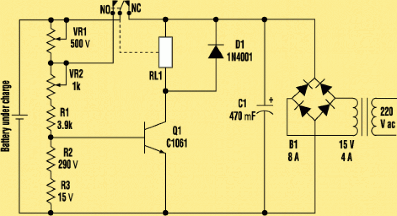
a single transistor smart battery charger
The electronic design features a smart battery charger schematic that utilizes only a single transistor. This design is notable as similar circuits typically employ simple integrated circuits. When the battery's charge level falls below a specific threshold voltage, the circuit...

Bedini SSG
The transistor activates, causing the magnet to move away. When the transistor deactivates, the energy stored in the coil collapses, directing its flow into the charging battery. As the next magnet approaches, the cycle repeats. This process effectively recaptures energy...
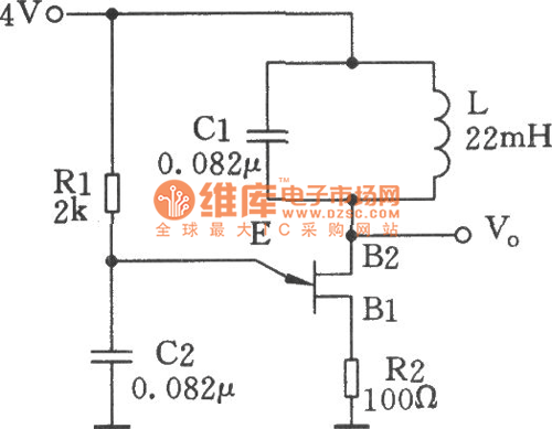
Single-junction transistor sine wave oscillator circuit
The single-junction transistor is commonly utilized in sawtooth and pulse generators, and it can also be configured to create a basic sine wave generation circuit. As an oscillator circuit composed of discrete components, it requires a minimal number of parts....
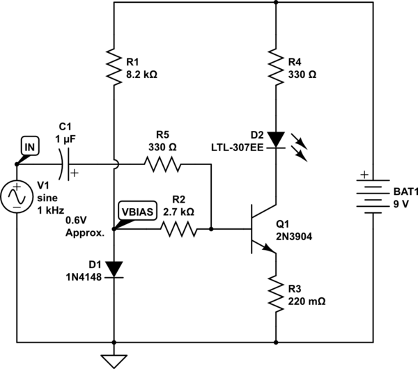
led How do I amplify a dc voltage that is too weak to trigger the base in a transistor
The goal is to take the voltage output from a 3.5mm audio jack and use it to light up an LED based on the audio voltage levels. The left audio channel will be connected to the base of a 2222N...

metal detector circuit
This circuit diagram represents a low-cost metal detector utilizing a single transistor circuit in conjunction with an old pocket radio. It operates as a Colpitts oscillator functioning within the medium band frequency range, with the radio tuned to the same...
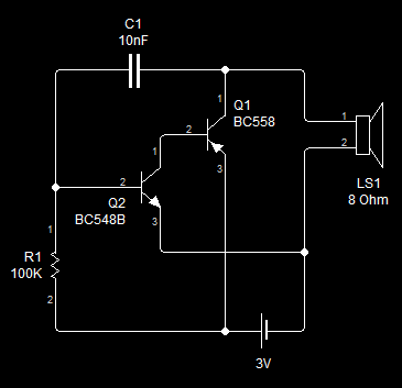
Very Simple Oscillator
This is the first oscillator that was built. Various resources such as books, magazines, and online schematics were reviewed. Most of the designs encountered were either Colpitts or Hartley oscillators. While these designs are relatively straightforward, they require specific inductors,...
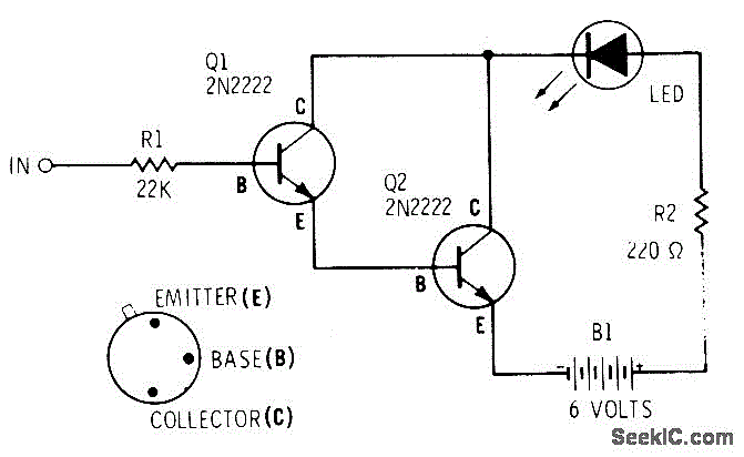
DARLINGTON LOGIC PROBE
A two-transistor Darlington connection offers a very high input impedance, ensuring that it does not load the logic circuit being monitored. This configuration drives an LED that illuminates when a logic high (1) is present at the input.
The two-transistor Darlington...

One transistor audio mixer (2N3563)
This circuit mixer features internal amplification using a 2N3563 transistor. Two input signals can be independently adjusted via VRI and VR2. The VR3 balance control allows for the attenuation of one signal while the other remains active. Additionally, the transistor...
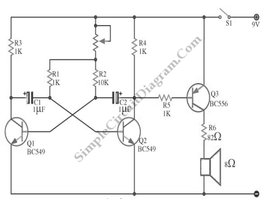
Simple Metronome With Transistors
A flip-flop, functioning as an astable multivibrator, can be utilized to generate timing signals in music applications such as a metronome. This can be achieved by adjusting the transistor bias resistor with a value of 100k.
The astable multivibrator configuration of...