


Sound-activated-decoder
#sound-activated
#piezo transducer
#op amp
#frequency-selective
#tone-decoder
#oscillator
#audio tones
#resonant frequency
#optocouplers
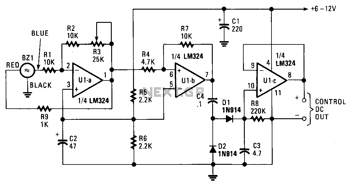
Description: The piezo transducer functions as both a sound pickup device and a frequency-selective filter. By adjusting the gain of the operational amplifiers (op-amps), the oscillator can be configured as a sensitive and frequency-selective tone decoder circuit. When the gain of U1a is set just below the self-oscillation threshold, the transducer becomes responsive to acoustically coupled audio tones that occur at or near its resonant frequency. The output of the circuit can be utilized to activate optocouplers, drive relay circuits, or control nearly any DC-operated circuit. The DC signal at the output of U1c varies from 0 to over 6 V, depending on the input signal level. An unusual application for the sound-activated decoder is in extremely high-noise environments, where conventional broadband microphone pickup would be ineffective. Since piezo transducers respond only to frequencies within a very narrow bandwidth, minimal noise is transmitted through the transducer.
The circuit design incorporates a piezo transducer, which serves as the primary sensor for sound detection. The transducer is connected to an operational amplifier (U1a), configured to amplify the signal while maintaining sensitivity to specific frequencies. The gain setting of U1a is critical; it must be adjusted to a level just below self-oscillation to ensure that the circuit remains responsive to desired audio tones without producing unwanted oscillations.
Following the first stage of amplification, the signal is processed by additional operational amplifiers (U1b and U1c) to further refine the output. U1b may serve as a band-pass filter, allowing only frequencies around the resonant frequency of the piezo transducer to pass through, effectively filtering out extraneous noise. The final output from U1c provides a DC voltage that varies based on the amplitude of the incoming audio signal, which can be interfaced with various control systems.
The versatility of this circuit is exemplified in its ability to activate optocouplers or drive relay circuits, making it suitable for a range of applications, including automation and control systems. The ability to operate effectively in high-noise environments is a significant advantage, as the narrow frequency response of the piezo transducer minimizes the impact of background noise, allowing for accurate sound detection in challenging conditions. This feature makes the circuit particularly valuable in industrial settings or areas with significant acoustic interference, where traditional sound detection methods may fail.The piezo transducer operates as a sound-pickup device as well as a frequency-selective filter. By controlling the gain of the op amps, the oscillator can be transformed into a sensitive and frequency-selective tone-decoder circuit. With the gain of U1a set just below the point of self oscillation, the transducer becomes sensitive to acoustically coupled audio tones that occur at or near its resonant frequency.
The circuit"s output can be used to activate optocouplers, drive relay circuits, or to control almost any de-operated circuit. The de signal at the output of U1c varies with 0 to over 6 V, depending on the inputsignal level. One unusual application for the sound-activated decoder would be in extremely high-noise environments, where normal broadband microphone pickup would be useless. Because piezo transducers respond only to frequencies within a very narrow bandwidth, little if any of the noise would get through the transducer.
The circuit design incorporates a piezo transducer, which serves as the primary sensor for sound detection. The transducer is connected to an operational amplifier (U1a), configured to amplify the signal while maintaining sensitivity to specific frequencies. The gain setting of U1a is critical; it must be adjusted to a level just below self-oscillation to ensure that the circuit remains responsive to desired audio tones without producing unwanted oscillations.
Following the first stage of amplification, the signal is processed by additional operational amplifiers (U1b and U1c) to further refine the output. U1b may serve as a band-pass filter, allowing only frequencies around the resonant frequency of the piezo transducer to pass through, effectively filtering out extraneous noise. The final output from U1c provides a DC voltage that varies based on the amplitude of the incoming audio signal, which can be interfaced with various control systems.
The versatility of this circuit is exemplified in its ability to activate optocouplers or drive relay circuits, making it suitable for a range of applications, including automation and control systems. The ability to operate effectively in high-noise environments is a significant advantage, as the narrow frequency response of the piezo transducer minimizes the impact of background noise, allowing for accurate sound detection in challenging conditions. This feature makes the circuit particularly valuable in industrial settings or areas with significant acoustic interference, where traditional sound detection methods may fail.The piezo transducer operates as a sound-pickup device as well as a frequency-selective filter. By controlling the gain of the op amps, the oscillator can be transformed into a sensitive and frequency-selective tone-decoder circuit. With the gain of U1a set just below the point of self oscillation, the transducer becomes sensitive to acoustically coupled audio tones that occur at or near its resonant frequency.
The circuit"s output can be used to activate optocouplers, drive relay circuits, or to control almost any de-operated circuit. The de signal at the output of U1c varies with 0 to over 6 V, depending on the inputsignal level. One unusual application for the sound-activated decoder would be in extremely high-noise environments, where normal broadband microphone pickup would be useless. Because piezo transducers respond only to frequencies within a very narrow bandwidth, little if any of the noise would get through the transducer.
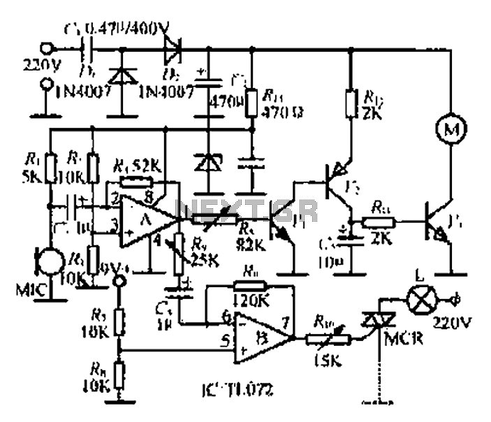
An electronic music rotating lights circuit
A microphone (MIC) is used to capture sound, which is then converted into a voltage signal. An operational amplifier (op-amp A) acts as a buffer; one output is directed to a motor drive circuit to control the motor's rotation in...
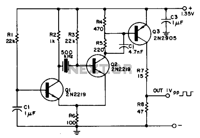
Oscillator operates from one cell
The circuit is powered by a single 1.35 V mercury cell and provides a 1 V square-wave output. The crystal acts as a tuned circuit between transistors Q1 and Q2, which are connected in a common-emitter configuration. Positive feedback is...
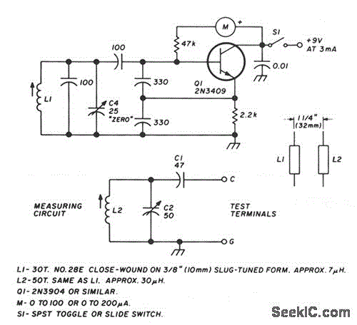
LC CHECKER
The circuit operates on the principle of the grid-dip or absorption effect, which takes place when a parallel resonant circuit is coupled to an oscillator operating at the same frequency. Transistor Q1 functions within a standard Colpitts oscillator circuit, maintaining...

Sound-Activated Lamp (Relay Switch)
This simple circuit shown in the schematic diagram activates the switch using sound. This circuit can be used for various applications, such as automatic switching.
The circuit utilizes a sound sensor, which is typically a microphone or a piezoelectric sensor, to...
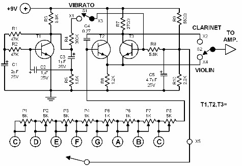
simple electronic organ
This electronic organ is simple to construct and can provide hours of enjoyment, particularly for children. The circuit is fundamentally an emitter-coupled oscillator consisting of transistors T2 and T3. A square wave voltage can be sampled from the collector of...
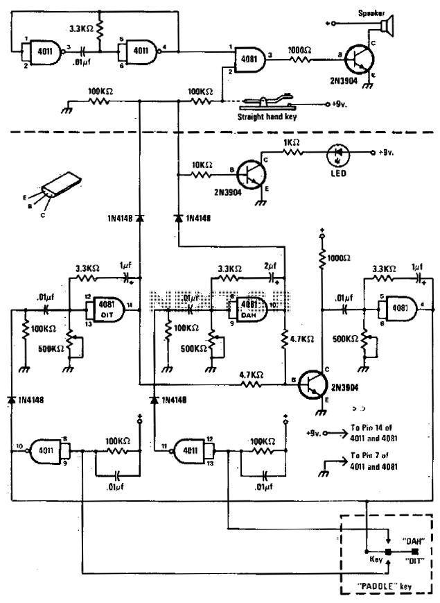
Code practice oscillator
The circuit comprises a basic oscillator (above the dashed line) and an automatic keyer (below the dashed line). The unit can be utilized with either a straight hand key or a paddle key for automatic operation.
The described circuit integrates two...
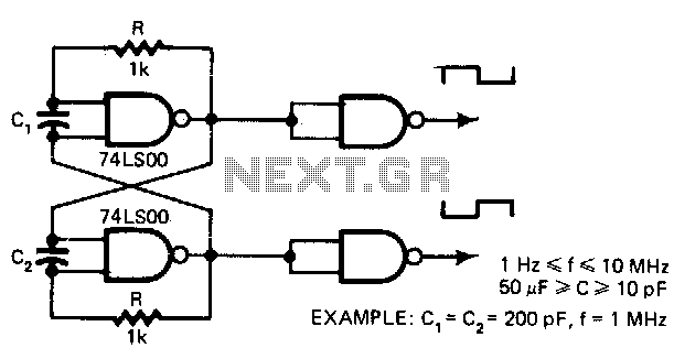
5-V-oscillator
This low-cost oscillator is consistently self-starting and capable of operating from over 1 Hz to 10 MHz, requiring only five components. The period of oscillation can be calculated using the relationship: P = 5 x 10^3 C seconds when C...
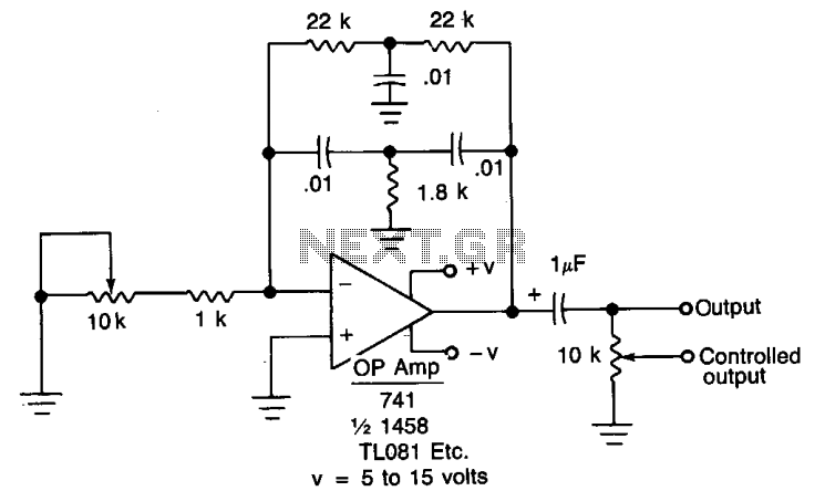
Oscillator IIV
When the oscillator is connected to a DC circuit, a DC blocking capacitor should be connected in series with the potentiometer's wiper arm. For finer output control, a 10 kΩ potentiometer can be added.
In this circuit configuration, the oscillator generates...
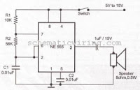
ring bell electronic circuit
This circuit generates an oscillating frequency of approximately 1 kHz, which can be adjusted by changing the value of resistor R1. The speaker will emit a continuous beep sound at this frequency.
The circuit utilizes a basic oscillator configuration, likely...