


Stereo demodulator
#stereo demodulator
#LM1310
#composite MPX
#left and right outputs
#oscillator
#76 kHz
#19 kHz
#audio signal
#demodulation
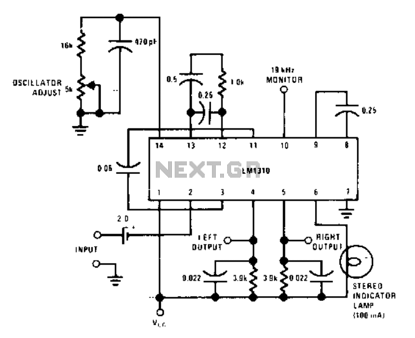
Description: This circuit utilizes a single integrated circuit, the LM1310, to provide left and right outputs from a composite MPX stereo signal. The oscillator adjust resistor R1 is configured for 76 kHz, which corresponds to 19 kHz at pin 10.
The LM1310 is a dedicated stereo demodulator designed for decoding multiplexed stereo signals. It effectively separates the left and right audio channels from a composite signal, making it suitable for applications in audio processing and broadcasting. The circuit's performance is heavily influenced by the choice of components, particularly the capacitor C1, which should be selected as a silver mica or NPO ceramic capacitor to ensure stability and low distortion in the audio output.
In this configuration, the oscillator circuit within the LM1310 generates a frequency of 76 kHz, which is essential for accurately demodulating the multiplexed signal. The resistor R1 plays a crucial role in setting this frequency, and any variations in its value can significantly affect the performance of the circuit. The output pins provide the separated left and right audio signals, which can be further processed or amplified as needed.
For optimal performance, it is important to maintain proper grounding and shielding in the circuit layout to minimize noise and interference. The selection of high-quality components, particularly in the signal path, will enhance the overall fidelity of the audio output. The design can be adapted for various applications, including FM radio receivers, stereo audio systems, and other multimedia devices requiring stereo signal processing.This circuit uses a single IC LM1310 to proyide left and right outputs from a composite MPX stereo signal. Oscillator adjust Rl is set for 76 kHz (19 kHz at pin 10). C1 should be a silver mica or NPO ceramic capacitor.
The LM1310 is a dedicated stereo demodulator designed for decoding multiplexed stereo signals. It effectively separates the left and right audio channels from a composite signal, making it suitable for applications in audio processing and broadcasting. The circuit's performance is heavily influenced by the choice of components, particularly the capacitor C1, which should be selected as a silver mica or NPO ceramic capacitor to ensure stability and low distortion in the audio output.
In this configuration, the oscillator circuit within the LM1310 generates a frequency of 76 kHz, which is essential for accurately demodulating the multiplexed signal. The resistor R1 plays a crucial role in setting this frequency, and any variations in its value can significantly affect the performance of the circuit. The output pins provide the separated left and right audio signals, which can be further processed or amplified as needed.
For optimal performance, it is important to maintain proper grounding and shielding in the circuit layout to minimize noise and interference. The selection of high-quality components, particularly in the signal path, will enhance the overall fidelity of the audio output. The design can be adapted for various applications, including FM radio receivers, stereo audio systems, and other multimedia devices requiring stereo signal processing.This circuit uses a single IC LM1310 to proyide left and right outputs from a composite MPX stereo signal. Oscillator adjust Rl is set for 76 kHz (19 kHz at pin 10). C1 should be a silver mica or NPO ceramic capacitor.
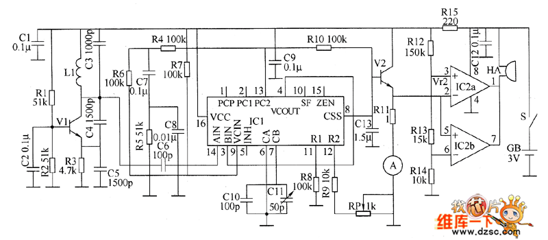
Metal detector circuit diagram 8
The metal detector circuit consists of a probe oscillator, a PLL (phase-locked loop) circuit, and an audio alarm circuit. The probe oscillator includes a detection coil (L), transistor (V1), and several resistors (R1 to R3) and capacitors (C1 to C5)....
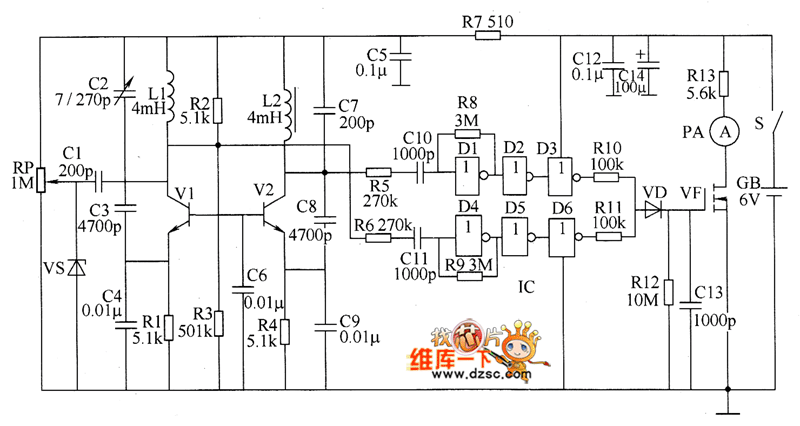
Metal detector circuit diagram 6
The metal detector circuit consists of several key components including the probe oscillator, reference oscillator, oscillation signal processor, mixing amplifier, and ammeter PA. The probe oscillator is made up of the oscillating tube VI, exploration coil L1, capacitors C1 to...
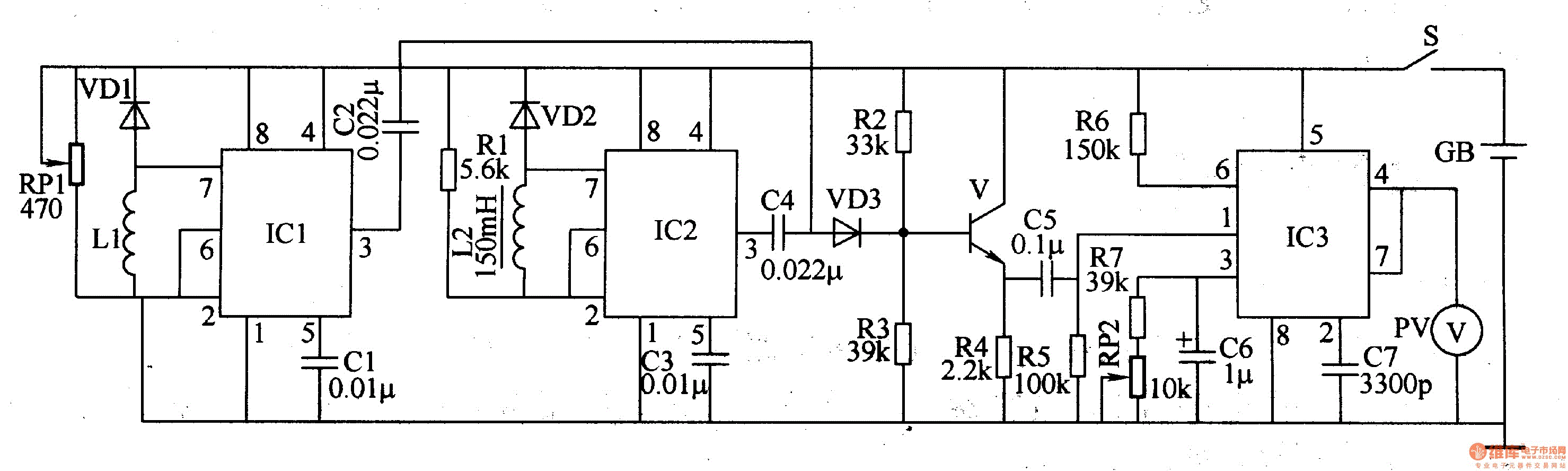
Metal detector 4
The metal detector circuit comprises a detection oscillator, a reference oscillator, a mixer, and a signal display, as illustrated in Figure 8-70. The detection oscillator circuit is made up of the time base oscillator IC1, inductor L1, potentiometer RP1, diode...
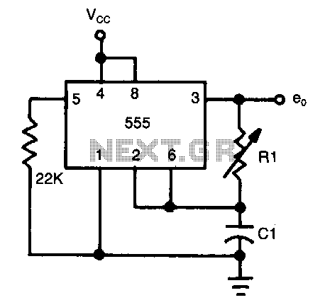
Half-duty-cycle-oscillator
The frequency of oscillation depends on the Rl/Cl time constant, allowing for frequency adjustment by varying Rl. This is a basic circuit.
The described circuit operates based on the relationship between resistance (Rl) and capacitance (Cl), which together form a time...
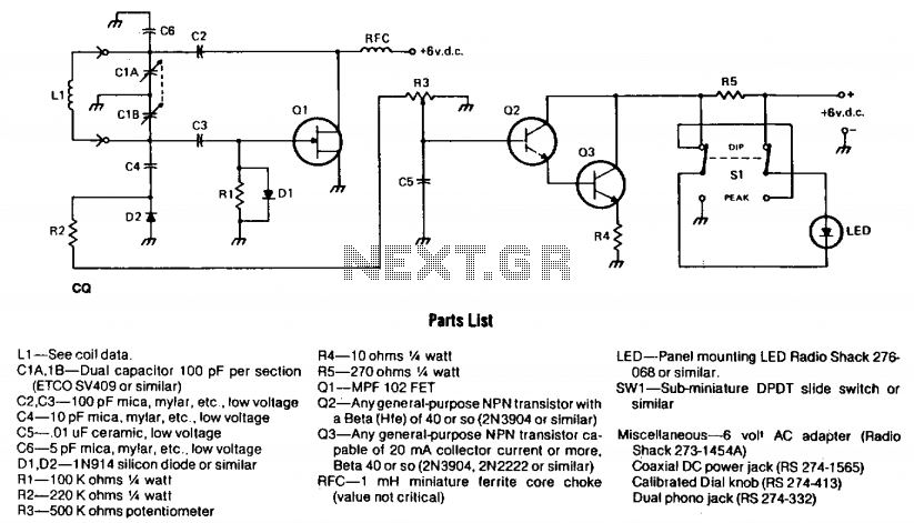
Little dipper
The circuit consists of two fundamental components: the oscillator and the detector. The oscillator employs a Field Effect Transistor (FET) in a Colpitts configuration. The energy circulating within the oscillator's tank is coupled through capacitor C4 to the detector circuit,...
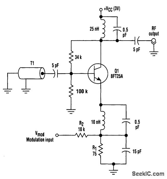
FM HF OSCILLATOR WITH NO VARACTOR
This circuit utilizes base-charging capacitance modulation instead of a varactor to frequency-modulate a high-frequency oscillator. This approach eliminates the significant voltage change required by a varactor, which can pose challenges in battery-powered systems with limited supply voltages. T1 serves as...
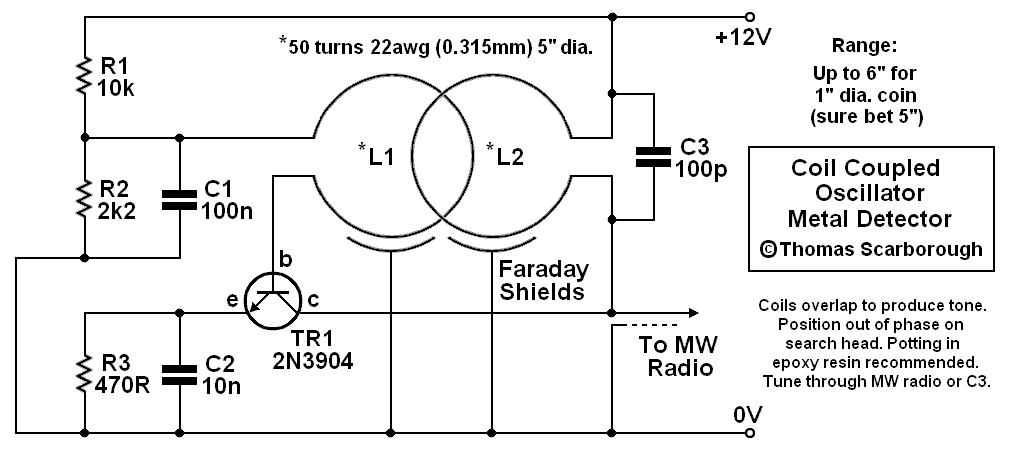
coil coupled operation metal
The metal detector presented may represent a new category in its field. After some exposure, it has been recognized as such by those familiar with it. This device is based on a standard transformer coupled oscillator (TCO), which is why...
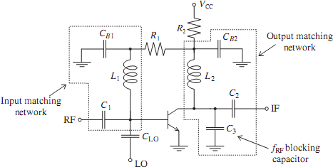
Oscillators and Mixers
The emergence of modern radio and radar systems has created a demand for stable harmonic oscillations at specific carrier frequencies to facilitate the necessary modulation and mixing conditions. While early carrier frequencies primarily operated in the low to mid MHz...
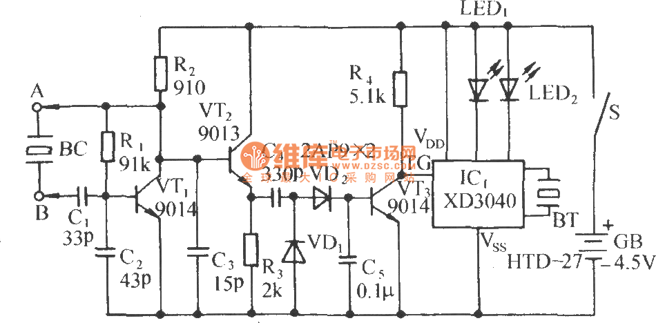
Acousto-optic detector circuit to measure the crystal
The circuit consists of a capacitance three-point oscillator, an isolation level, a voltage doubler rectifier circuit, a stereo sound circuit, and a flash display circuit. It can detect the quality of a crystal; a good crystal will emit a "Didi"...