


Tech Gear Multi-Voice Changer
#voice changer
#OpAmp
#microphone
#speaker
#frequency modulation
#audio effects
#signal amplification
#pitch control
Description: The Voice Changer features two distinct inputs: a microphone and switches. It processes the input signal and sends it to an operational amplifier (OpAmp) for amplification before outputting to a speaker. The output signal's frequency is modified based on the selected voice effect. Basic effects, such as low pitch and high pitch, adjust the frequency either upward or downward. In robotic mode, the signal transitions from low frequency to high frequency and oscillates, producing a robotic sound effect. The accompanying table illustrates the frequency of the output signal sent to the speaker.
The Voice Changer circuit is designed to manipulate audio signals captured from a microphone and modify them based on user-selected effects. The microphone serves as the primary input source, converting acoustic signals into electrical signals. The switches allow users to select different voice effects, influencing how the audio signal is processed.
Upon receiving the input from the microphone, the signal is routed to an operational amplifier (OpAmp). This component is crucial for amplifying the weak audio signal to a level suitable for further processing and output. The OpAmp is configured to provide gain, which enhances the overall volume of the output sound.
The circuit employs a frequency modulation technique to achieve various voice effects. For basic effects like low pitch and high pitch, the circuit utilizes simple frequency shifting methods. When low pitch is selected, the circuit reduces the frequency of the input signal, while high pitch raises it.
In robotic mode, the circuit incorporates a more complex modulation technique. It rapidly oscillates the frequency of the signal between low and high values, creating a synthetic robotic sound. This effect is achieved by using a combination of oscillators and filters that modify the frequency characteristics of the signal in real-time.
The output of the circuit is then sent to a speaker, which converts the amplified electrical signal back into sound waves. The final output frequency, which varies depending on the selected effect, can be referenced in the accompanying table, detailing the specific frequency ranges associated with each voice effect. This comprehensive system allows for versatile sound manipulation, catering to various audio applications and user preferences.The Voice Changer has two different inputs, the microphone and the switches. The Voice Changer then outputs a signal to an OpAmp to amplify the signal being sent to the speaker. The frequency of this signal is changed depending on what voice effect is turned on. The more simple voice effects such as low pitch and high pitch only change the frequen cy up or down. When the device is in robotic mode the signal changes from a low frequency to a high frequency and oscillates back and forth to create the robotic sound effect. The table below shows the frequency of the signal output to the speaker.
The Voice Changer circuit is designed to manipulate audio signals captured from a microphone and modify them based on user-selected effects. The microphone serves as the primary input source, converting acoustic signals into electrical signals. The switches allow users to select different voice effects, influencing how the audio signal is processed.
Upon receiving the input from the microphone, the signal is routed to an operational amplifier (OpAmp). This component is crucial for amplifying the weak audio signal to a level suitable for further processing and output. The OpAmp is configured to provide gain, which enhances the overall volume of the output sound.
The circuit employs a frequency modulation technique to achieve various voice effects. For basic effects like low pitch and high pitch, the circuit utilizes simple frequency shifting methods. When low pitch is selected, the circuit reduces the frequency of the input signal, while high pitch raises it.
In robotic mode, the circuit incorporates a more complex modulation technique. It rapidly oscillates the frequency of the signal between low and high values, creating a synthetic robotic sound. This effect is achieved by using a combination of oscillators and filters that modify the frequency characteristics of the signal in real-time.
The output of the circuit is then sent to a speaker, which converts the amplified electrical signal back into sound waves. The final output frequency, which varies depending on the selected effect, can be referenced in the accompanying table, detailing the specific frequency ranges associated with each voice effect. This comprehensive system allows for versatile sound manipulation, catering to various audio applications and user preferences.The Voice Changer has two different inputs, the microphone and the switches. The Voice Changer then outputs a signal to an OpAmp to amplify the signal being sent to the speaker. The frequency of this signal is changed depending on what voice effect is turned on. The more simple voice effects such as low pitch and high pitch only change the frequen cy up or down. When the device is in robotic mode the signal changes from a low frequency to a high frequency and oscillates back and forth to create the robotic sound effect. The table below shows the frequency of the signal output to the speaker.
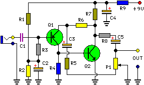
portable microphone preamplifier circuit schematic
This circuit is primarily designed to provide a microphone input for standard home stereo amplifiers. Utilizing a battery supply effectively eliminates the risk of low-frequency hum interference from mains power, simplifying the connection to the amplifier by removing the need...
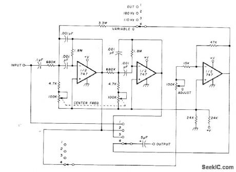
Filter Circuit
The circuit utilizing Optical Electronics 9803 operational amplifiers separates an audio frequency (AF) input signal into two outputs. The low-pass output allows frequencies from DC up to 10 Hz, while the high-pass output encompasses frequency content above 10 Hz, reaching...
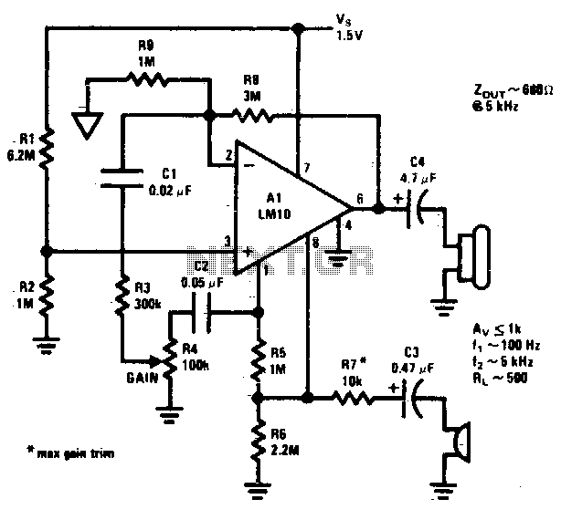
Microphone amplifier
This circuit operates from a 5 V DC source.
The described circuit is powered by a 5 V direct current (DC) supply, which is a common voltage level for many electronic devices and applications. The circuit may utilize various components such...
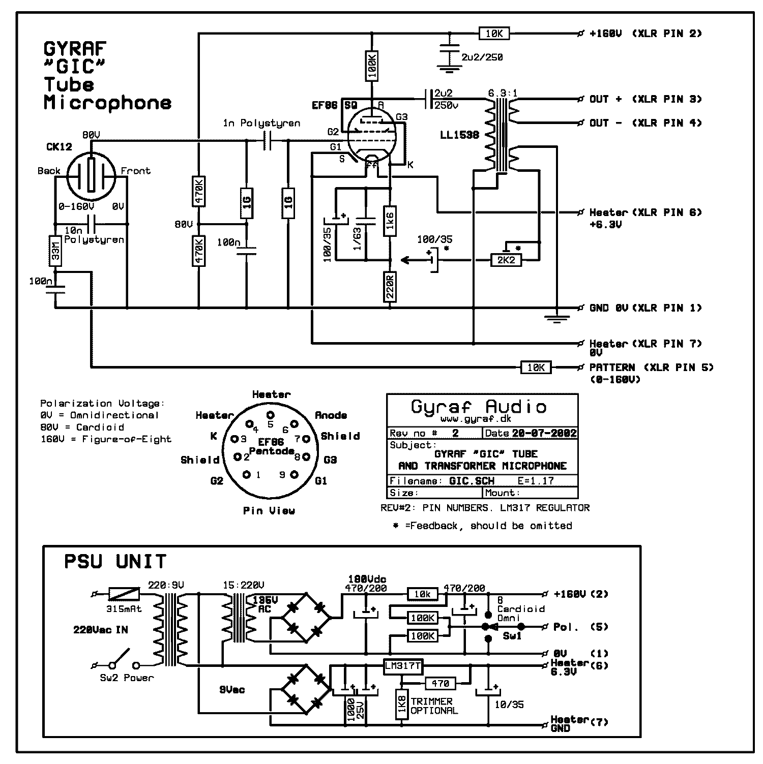
gic
The design resembles a combination of circuits from M49 and U47, utilizing the tube from U67. It features a true variable-pattern microphone capable of omnidirectional, cardioid, and figure-of-eight patterns. This is achieved by polarizing the front and back diaphragms of...
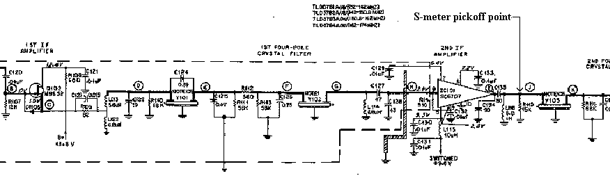
Motorola Micor S-meter Driver
The artwork style of the operational amplifier and the meter face suggests that it is an ACC design from an old issue of ACC Notes. The second image was scanned, and the text below was written from scratch. If the...
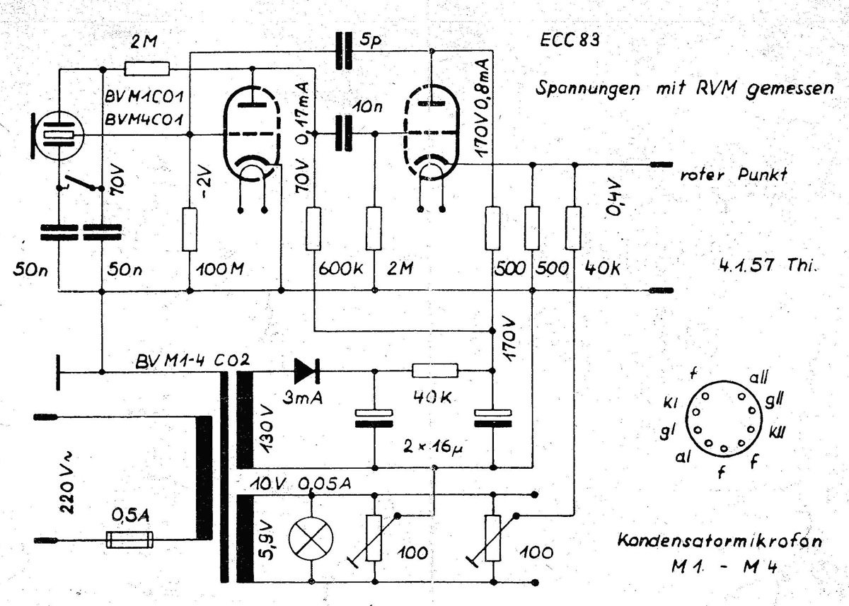
Microphones schematics and documents
The power supply is integrated into the base of the microphone, which may cause hum issues, even with the onboard potentiometer designed to nullify this effect. Consequently, the microphone features two cables: one for power and another for audio transmission....
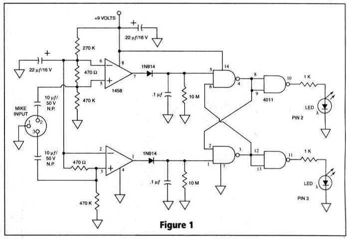
Build a Microphone Polarity Tester
Many things can go wrong in a modern recording studio, but few are as difficult to track down as reversed microphone polarity. When a microphone is placed in front of a sound source, a positive pressure on its diaphragm caused...

DIFFERENTIAL AC SIGNALS
Precision full-wave rectification of differential voltage is achieved by converting voltage to current for rectification and then reconverting to output voltage. One operational amplifier functions as a voltage-to-current converter, while the other serves as a current-to-current rectifier. This circuit is...
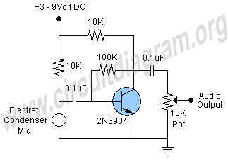
microphone preamp circuit
This schematic illustrates a highly sensitive microphone preamplifier circuit designed to amplify the gain of a microphone or enhance audio signals originating from a microphone. The circuit is straightforward, comprising only a few components, and can be assembled in a...