


The 145 Theremin
#theremin
#heterodyne
#oscillator
#musical instrument
#analog circuit
#audio synthesis
#electronic music
#DIY audio
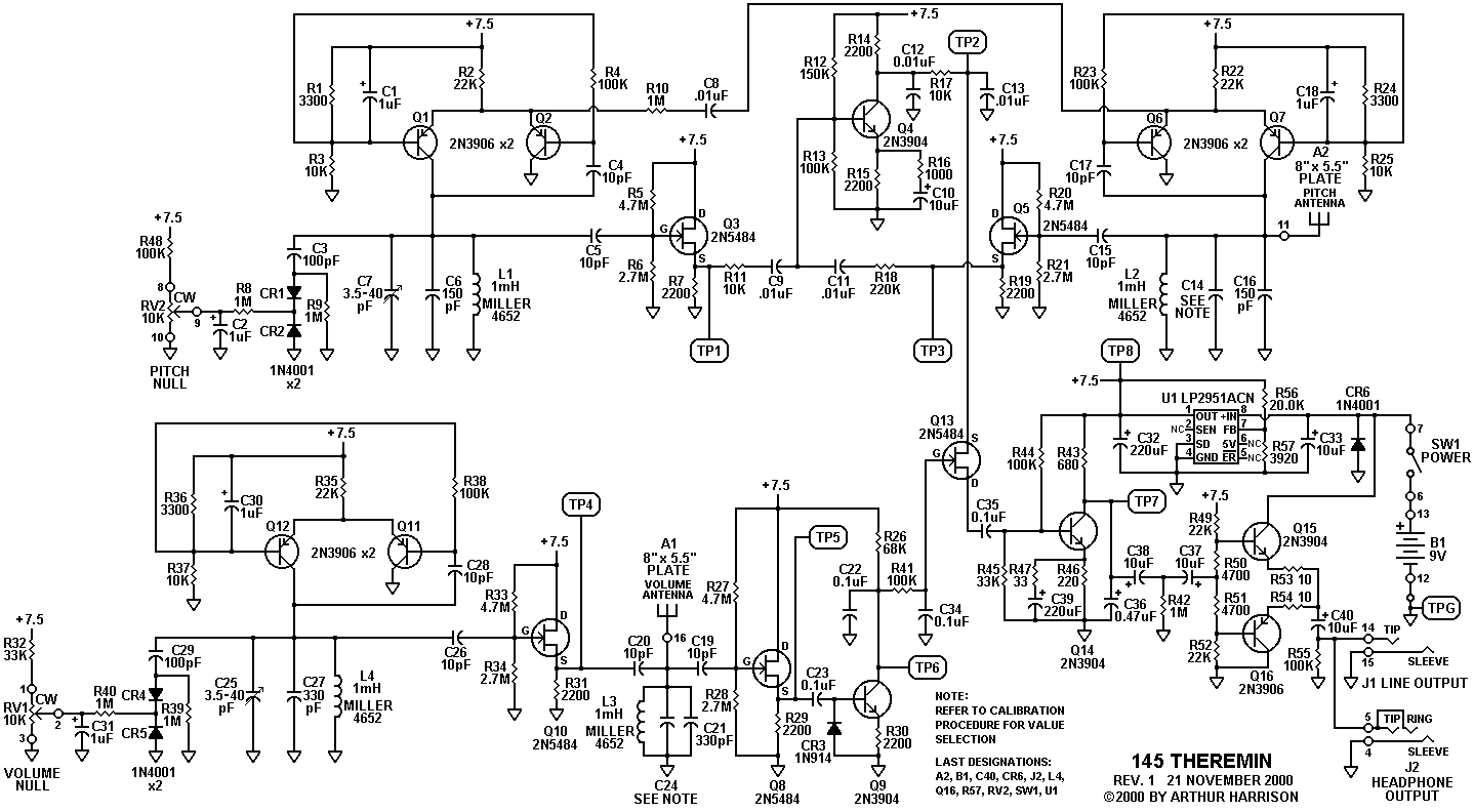
Description: Since the publication of the type 144 theremin project article in September 1998, many of these instruments have been successfully constructed. The 145 theremin retains a heterodyne topology similar to that used in the original instruments by Mr. Theremin, as seen in the 144 and its predecessor, the Southwest Technical Products model 142. The 145 theremin is similar to the 144 in most respects, except for the types of oscillators used. The oscillators in the 145 theremin are differential-pair types, while the 144 utilizes Colpitts types. The approximate operating frequencies for the 145 theremin are 270 kHz for the volume circuit and 360 kHz for the pitch circuit. Compared to the 144, the 145 exhibits improved pitch-arc linearity, with A440 occurring at about 10 inches of hand distance, compared to approximately 5 inches for the 144. The practical pitch range for the 145 is about 4.5 octaves. Inexpensive silicon rectifiers are employed as varactors, providing a volume oscillator tuning range of about 1200 Hz and a pitch reference oscillator tuning range of approximately 700 Hz. These frequencies typically vary within ±10 percent among instruments due to tolerances. In the new design, oscillator outputs are taken from the resonant L-C pairs, producing low-distortion sine waves. Weak coupling is established between the two pitch oscillators via C8 and R10 to induce a "lock" condition for zero-beat when the pitch hand is absent. The pitch oscillator levels at the mixer input are unequal, resulting in a significantly reduced mixer output amplitude compared to the 144.
The 145 theremin represents an evolution in theremin design, incorporating differential-pair oscillators that enhance both performance and sound quality. The choice of operating frequencies at 270 kHz for volume modulation and 360 kHz for pitch modulation ensures that the instrument maintains a wide dynamic range while allowing for precise control over pitch and volume. The improved pitch-arc linearity is a significant advancement, making the instrument more intuitive for performers, as they can achieve desired pitch changes with less hand movement.
The use of silicon rectifiers as varactors is a cost-effective solution that contributes to the overall tuning flexibility of the theremin. With a tuning range of 1200 Hz for volume and 700 Hz for pitch, musicians can explore a wide array of tonal possibilities. The ±10 percent frequency variation among different units indicates the importance of careful calibration and quality control during manufacturing.
In terms of signal processing, the output derived from the resonant L-C pairs is crucial for producing low-distortion sine waves, which are essential for maintaining the purity of the theremin's sound. The weak coupling mechanism implemented through components C8 and R10 ensures that the pitch oscillators can achieve a stable zero-beat condition, which is vital for maintaining pitch accuracy when the performer’s hands are not in proximity to the instrument.
The design also addresses the mixer input levels, which are intentionally unequal to reduce the output amplitude. This strategic approach minimizes potential distortion and enhances the overall tonal quality of the theremin, setting it apart from previous models like the 144. Overall, the 145 theremin showcases advancements in electronic design and engineering, resulting in a more refined and versatile instrument for musicians.Since the publication of the type 144 theremin project article in September, 1998, many of them have been successfully constructed. As in the 144, and its forerunner, the Southwest Technical Products model 142, the 145 theremin retains a heterodyne topology similar to that used by Mr.
Theremin in his original instruments. The 145 theremin is similar to the 144 in most respects, excepting the types of oscillators used. The 145 theremin oscillators are differential-pair types, in comparison to the Colpitts types in the 144. The approximate operating frequencies for the 145 theremin are 270kHz for the volume circuit and 360kHz for the pitch circuit.
Compared to the 144, the 145 has improved pitch-arc linearity, with A440 occurring at about 10 inches of hand distance, compared to about 5 inches for the 144. The practical pitch range for the 145 is about 4 1/2 octaves. Inexpensive silicon rectifiers are used as varactors to provide a volume oscillator tuning range of about 1200Hz and a pitch reference oscillator tuning range of about 700Hz.
These frequencies will typically vary within ±10 per-cent among instruments, due to tolerances. In the new design, oscillator outputs are taken from the resonant L-C pairs, and are low-distortion sine waves. Weak coupling is provided between the two pitch oscillators via C8 and R10 to induce a "lock" condition for zero-beat when the pitch hand is absent.
The pitch oscillator levels at the mixer input are unequal, and the mixer output amplitude is significantly reduced in comparison to the 144. This reduct
The 145 theremin represents an evolution in theremin design, incorporating differential-pair oscillators that enhance both performance and sound quality. The choice of operating frequencies at 270 kHz for volume modulation and 360 kHz for pitch modulation ensures that the instrument maintains a wide dynamic range while allowing for precise control over pitch and volume. The improved pitch-arc linearity is a significant advancement, making the instrument more intuitive for performers, as they can achieve desired pitch changes with less hand movement.
The use of silicon rectifiers as varactors is a cost-effective solution that contributes to the overall tuning flexibility of the theremin. With a tuning range of 1200 Hz for volume and 700 Hz for pitch, musicians can explore a wide array of tonal possibilities. The ±10 percent frequency variation among different units indicates the importance of careful calibration and quality control during manufacturing.
In terms of signal processing, the output derived from the resonant L-C pairs is crucial for producing low-distortion sine waves, which are essential for maintaining the purity of the theremin's sound. The weak coupling mechanism implemented through components C8 and R10 ensures that the pitch oscillators can achieve a stable zero-beat condition, which is vital for maintaining pitch accuracy when the performer’s hands are not in proximity to the instrument.
The design also addresses the mixer input levels, which are intentionally unequal to reduce the output amplitude. This strategic approach minimizes potential distortion and enhances the overall tonal quality of the theremin, setting it apart from previous models like the 144. Overall, the 145 theremin showcases advancements in electronic design and engineering, resulting in a more refined and versatile instrument for musicians.Since the publication of the type 144 theremin project article in September, 1998, many of them have been successfully constructed. As in the 144, and its forerunner, the Southwest Technical Products model 142, the 145 theremin retains a heterodyne topology similar to that used by Mr.
Theremin in his original instruments. The 145 theremin is similar to the 144 in most respects, excepting the types of oscillators used. The 145 theremin oscillators are differential-pair types, in comparison to the Colpitts types in the 144. The approximate operating frequencies for the 145 theremin are 270kHz for the volume circuit and 360kHz for the pitch circuit.
Compared to the 144, the 145 has improved pitch-arc linearity, with A440 occurring at about 10 inches of hand distance, compared to about 5 inches for the 144. The practical pitch range for the 145 is about 4 1/2 octaves. Inexpensive silicon rectifiers are used as varactors to provide a volume oscillator tuning range of about 1200Hz and a pitch reference oscillator tuning range of about 700Hz.
These frequencies will typically vary within ±10 per-cent among instruments, due to tolerances. In the new design, oscillator outputs are taken from the resonant L-C pairs, and are low-distortion sine waves. Weak coupling is provided between the two pitch oscillators via C8 and R10 to induce a "lock" condition for zero-beat when the pitch hand is absent.
The pitch oscillator levels at the mixer input are unequal, and the mixer output amplitude is significantly reduced in comparison to the 144. This reduct
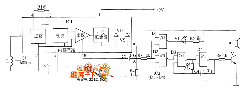
Metal detector circuit diagram 5
The metal detector circuit comprises an oscillator and a sound-light alarm circuit. The oscillator circuit includes an inductor (L), a capacitor (C1), a sensor switch integrated circuit (IC1) that integrates the oscillator, detector, comparator circuit, and peripheral components. The sound-light...
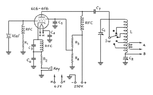
The Ecology of the Oscillator Transmitter
An oscillator-only transmitter appears to be the simplest way to access the radio airwaves; however, it presents several challenges as part of a transmitting and receiving station. The issue of finding an adequate crystal-controlled transmitter for newcomers wishing to operate...
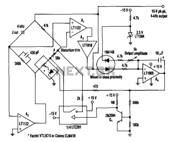
Very Low Distortion Oscillator
This oscillator utilizes a bridge circuit with an optoisolator functioning as a gain-control device. The resultant distortion can be maintained at 9 ppm (0.0009%) with appropriate adjustments.
The oscillator circuit described operates using a bridge configuration, which is a common approach...
Last-cycle-completing-gated-oscillator
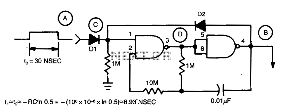
Regenerative feedback at capacitor C allows the oscillator to complete its timing cycle instead of shutting off immediately. The integrated circuit (IC) used was a CD4011AE, although an equivalent IC will also function.
The described circuit utilizes regenerative feedback to enhance...
Oscillators and Mixers
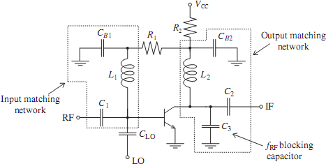
The emergence of modern radio and radar systems has created a demand for stable harmonic oscillations at specific carrier frequencies to facilitate the necessary modulation and mixing conditions. While early carrier frequencies primarily operated in the low to mid MHz...
Schematic Diagram Schema HO Train Model Lighthouse Flasher
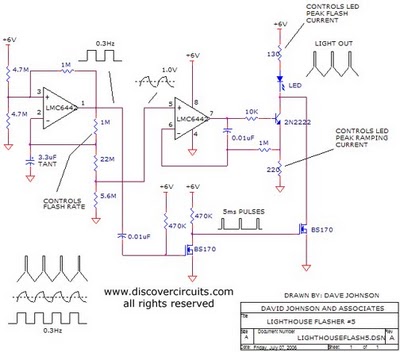
The aboriginal accessory forms a typical oscillator circuit that produces both a triangle waveform signal and a square wave signal. The triangle signal is fed into a voltage regulator circuit, which converts the triangle voltage signal to a triangle current...
coil coupled operation metal
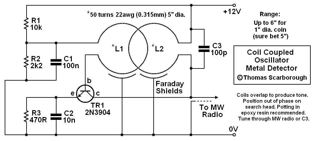
The metal detector presented may represent a new category in its field. After some exposure, it has been recognized as such by those familiar with it. This device is based on a standard transformer coupled oscillator (TCO), which is why...

Double oscillator metal detector
The circuit consists of two oscillators, both working at about 465 kHz. One uses an if transformer and the other uses an inductor (the search coil LI). The oscillators are coupled by a capacitor (10 pF). A beat note (produced...
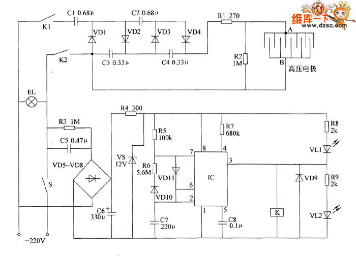
Electronic pests killing lamp circuit diagram 4
The electronic pest-killing lamp circuit comprises an oscillator, control circuit, high voltage generator, LED indicator circuit, and power supply circuit. The schematic diagram illustrates these components. The oscillator circuit includes a time-base integrated circuit (IC), resistors R5 to R7, diodes...