


Tone ringer
#tone ringer
#MC34012
#piezoelectric transducer
#relaxation oscillator
#frequency generator
#audio signal
#ac ringing signal
#warble tone
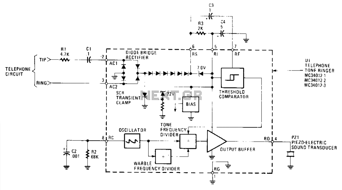
Description: The MC34012 tone-ringer chip derives its power by rectifying the AC ringing signal, which typically operates at 20 Hz and ranges from 70 to 130 volts RMS. This power is utilized for the tone generator and to drive a piezoelectric transducer. The resulting sound is a warble that oscillates between two frequencies, f0/4 (f0 - 4) and f0/5. The fundamental frequency, f0, is produced by a relaxation oscillator, with R2 and C2 serving as the frequency-setting components, allowing for a selectable range of 1 kHz to 10 kHz. By adjusting the values of R2 and/or C2, the clock frequency can be altered, thereby changing the warble frequencies. For instance, at a 4.40 kHz oscillator frequency, the MC34012-1 generates tones of 800 Hz and 1000 Hz with a warble rate of 12.5 Hz. The MC34012-2 produces tones of 1600 Hz and 2000 Hz at an 8.0 kHz oscillator frequency, also maintaining a 12.5 Hz warble frequency. The MC34012-3 outputs tones of 400 Hz and 500 Hz from a 2.0 kHz oscillator frequency, again with a 12.5 Hz warble rate. The MC34012 chip is available in three different configurations, each corresponding to a specific warble frequency rate of fo/320, fo/640, or fo/160, designated as MC34012-1, -2, and -3, respectively.
The MC34012 tone-ringer chip is designed for applications requiring an audible alert signal, leveraging its ability to convert an AC ringing signal into a sound output. The chip's architecture includes a power rectification stage that effectively transforms the incoming AC signal into a usable DC voltage for internal operations. This voltage powers both the tone generation circuitry and the piezoelectric transducer, which is responsible for producing sound.
The relaxation oscillator circuit is fundamental to the operation of the MC34012. By utilizing resistors and capacitors (specifically R2 and C2), the oscillator's frequency can be finely tuned within the specified range of 1 kHz to 10 kHz. This flexibility allows designers to customize the audio output based on application requirements. When R2 and C2 values are adjusted, they influence the time constant of the oscillator, thus changing the frequency of the output signal.
The warble sound produced by the MC34012 is characterized by alternating tones, which are defined by the relationships f0/4 and f0/5. This modulation creates a distinctive sound that can be perceived as more attention-grabbing compared to a single tone. The various configurations of the MC34012 (MC34012-1, MC34012-2, and MC34012-3) offer different warble rates, catering to diverse signaling needs. The choice of configuration enables the selection of specific tone pairs and warble rates, allowing for a range of auditory signals suitable for different applications, such as doorbells, alarms, or notification systems.
In summary, the MC34012 tone-ringer chip is a versatile solution for generating warbling tones from AC ringing signals, with adjustable frequency settings that enhance its adaptability for various electronic signaling applications. The integration of power rectification, tone generation, and sound output in a single chip streamlines the design process for engineers seeking to implement alert systems in their projects.The MC34012 tone-ringer chip derives its power by rectifying the ac ringing signal. That signal is normally at 20 Hz and measures between 70 and 130 volts rms. It uses that power for the tone generator and to drive the piezoelectric transducer. The sound that is produced is a warble that varies between two frequencies, f0/4 (f0 - 4) f0/5. The clock, or fundamental, frequency, f0, is generated by a relaxation oscillator. That oscillator has R2 and C2 as its frequency setting components providing a selectable range of 1 kHz to 10 kHz. Selecting different values for R2 and/or C2 changes the clock frequency, which in turn varies the warble frequencies.
For example: with a 4.40 kHz oscillator frequency, the MC34012-1 produces 800 Hz and 1000 Hz tones with a 12.5 Hz warble rate. The MC34012-2 generates 1600 Hz and 2000 Hz tones with a similar 12.5 Hz warble frequency from an 8.0 kHz oscillator frequency.
MC34012-3 will produce 400 Hz and 500 Hz tones with a 12.5 warble rate from a 2.0 kHz oscillator frequency. The MC34012 chip comes in three different warble rates at which the warble frequencies (f0/4, f0/5) are varied.
These warble rates are fo/320, fo/640, or fo/160 and the different chips are designated as MC34012-1, -2, and -3, respectively.
The MC34012 tone-ringer chip is designed for applications requiring an audible alert signal, leveraging its ability to convert an AC ringing signal into a sound output. The chip's architecture includes a power rectification stage that effectively transforms the incoming AC signal into a usable DC voltage for internal operations. This voltage powers both the tone generation circuitry and the piezoelectric transducer, which is responsible for producing sound.
The relaxation oscillator circuit is fundamental to the operation of the MC34012. By utilizing resistors and capacitors (specifically R2 and C2), the oscillator's frequency can be finely tuned within the specified range of 1 kHz to 10 kHz. This flexibility allows designers to customize the audio output based on application requirements. When R2 and C2 values are adjusted, they influence the time constant of the oscillator, thus changing the frequency of the output signal.
The warble sound produced by the MC34012 is characterized by alternating tones, which are defined by the relationships f0/4 and f0/5. This modulation creates a distinctive sound that can be perceived as more attention-grabbing compared to a single tone. The various configurations of the MC34012 (MC34012-1, MC34012-2, and MC34012-3) offer different warble rates, catering to diverse signaling needs. The choice of configuration enables the selection of specific tone pairs and warble rates, allowing for a range of auditory signals suitable for different applications, such as doorbells, alarms, or notification systems.
In summary, the MC34012 tone-ringer chip is a versatile solution for generating warbling tones from AC ringing signals, with adjustable frequency settings that enhance its adaptability for various electronic signaling applications. The integration of power rectification, tone generation, and sound output in a single chip streamlines the design process for engineers seeking to implement alert systems in their projects.The MC34012 tone-ringer chip derives its power by rectifying the ac ringing signal. That signal is normally at 20 Hz and measures between 70 and 130 volts rms. It uses that power for the tone generator and to drive the piezoelectric transducer. The sound that is produced is a warble that varies between two frequencies, f0/4 (f0 - 4) f0/5. The clock, or fundamental, frequency, f0, is generated by a relaxation oscillator. That oscillator has R2 and C2 as its frequency setting components providing a selectable range of 1 kHz to 10 kHz. Selecting different values for R2 and/or C2 changes the clock frequency, which in turn varies the warble frequencies.
For example: with a 4.40 kHz oscillator frequency, the MC34012-1 produces 800 Hz and 1000 Hz tones with a 12.5 Hz warble rate. The MC34012-2 generates 1600 Hz and 2000 Hz tones with a similar 12.5 Hz warble frequency from an 8.0 kHz oscillator frequency.
MC34012-3 will produce 400 Hz and 500 Hz tones with a 12.5 warble rate from a 2.0 kHz oscillator frequency. The MC34012 chip comes in three different warble rates at which the warble frequencies (f0/4, f0/5) are varied.
These warble rates are fo/320, fo/640, or fo/160 and the different chips are designated as MC34012-1, -2, and -3, respectively.
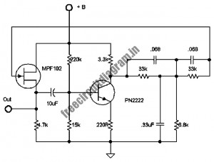
Circuit Diagram Of 60 Hz Frequency Signal Generator
The following circuit illustrates a stable 60 Hz frequency signal generator circuit diagram. Features include a 0.068 µF capacitor incorporated within a feedback loop, allowing for DC-to-AC conversion.
This circuit is designed to generate a stable 60 Hz sine wave output,...
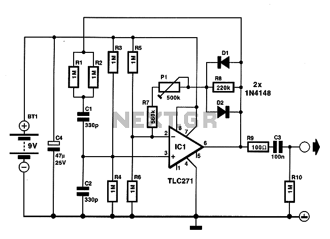
Low energy consumption audio signal generator
On occasions when it is necessary to determine if an amplifier is functioning, the most effective tool is an acoustic signal source with a frequency around 1 kHz. The specifications can be considered flexible, as rapid tests typically do not...
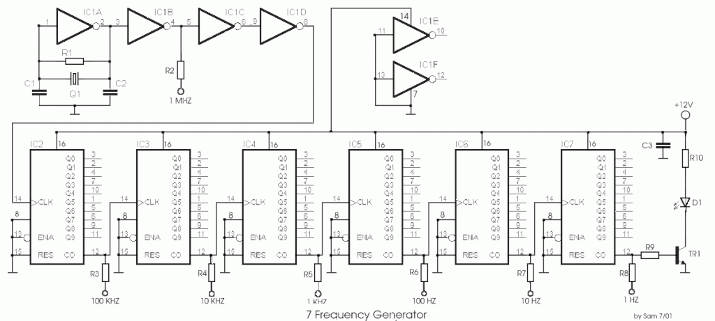
7 Standard Step Frequency from Frequency Generator
The circuit was designed to create a frequency generator that consists of seven steps during operation. It includes a crystal oscillator, which is an electronic circuit made of...
The frequency generator circuit operates through a series of seven distinct steps, each...
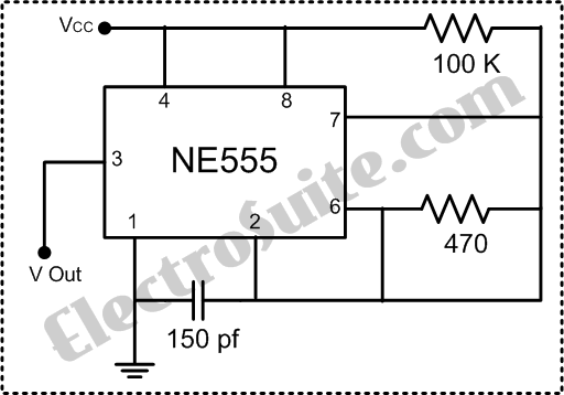
Generator circuit
The 60 Hz frequency generator circuit is essential for creating inverters or hardware related to AC current voltage. This 60 Hz frequency generator is straightforward and highly accurate, producing a precision square wave output. The core of this generator is...
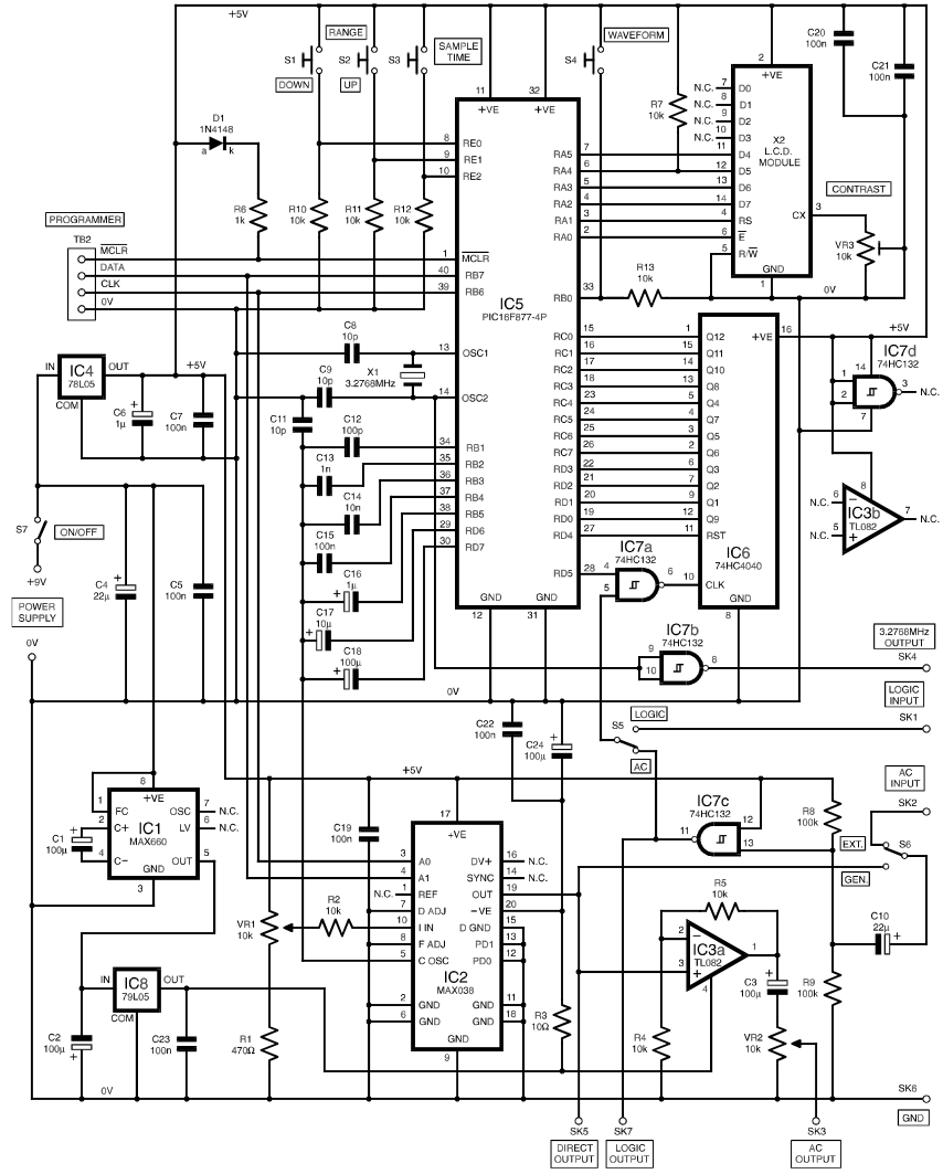
Frequency Generator Counter
The functional generator is a device that any well-equipped electronic lab should possess, even if it is not frequently used. However, its convenience is greatly appreciated when needed. This scheme was published in the magazine Everyday Practical Electronics, 2000, issue...
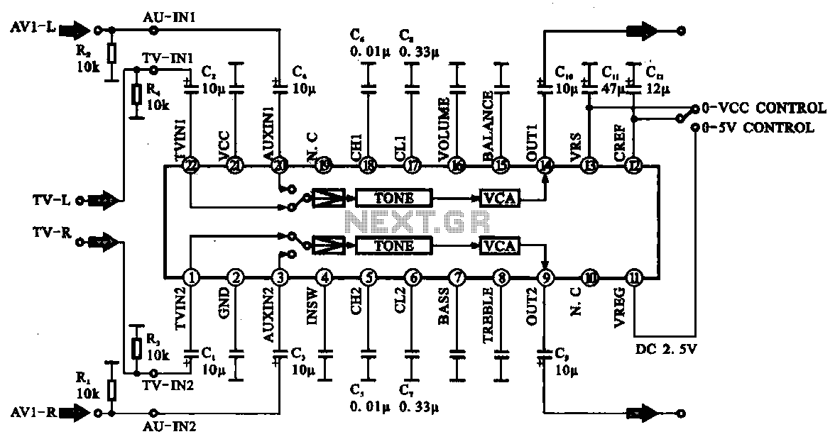
Audio signal control circuit
Audio signal control circuit. It illustrates a typical audio signal control circuit where two audio signals enter the integrated circuit through switching and tone controls (treble and bass), subsequently adjusting the output sent to the audio power amplifier.
The audio signal...
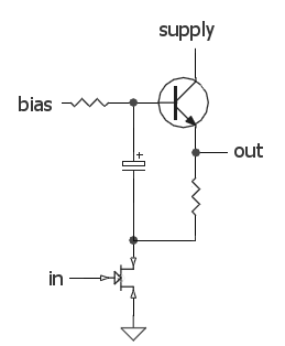
DC biasing audio signal
The audio source will be a line-level audio signal ranging from -2V to +2V AC, which will be passed through a 220µF coupling capacitor followed by a two-pole low-pass filter (RC). The signal will be processed by an Analog-to-Digital Converter...
Audio Signal Strength Detector/Converter
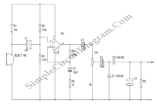
Below is the schematic diagram of an audio input module. This module is capable of producing a DC output voltage that is proportional to the amplitude of the input signal.
The audio input module typically consists of several key components that...

Phantastron
A relaxation oscillator that produces linearly varying voltage with a low nonlinear distortion factor. Phantastrons can function in either slave or self-oscillating modes. Phantastrons designed for large variable voltage ranges (tens to hundreds of volts) typically utilize electron tubes, such...