


Turbo Bass (Booster)
#bass booster
#op-amp
#active circuit
#low frequency
#sound enhancement
#audio amplifier
#signal processing
#sound modification
#audio filter
#bass control
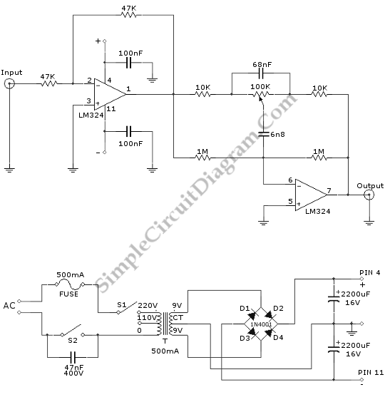
Description: This is a Turbo Bass circuit. Using this circuit, low-frequency sound signals (bass) can be amplified. This circuit is an active circuit. The first op-amp...
The Turbo Bass circuit is designed to enhance low-frequency audio signals, specifically targeting the bass range to provide a richer sound experience. The circuit utilizes an operational amplifier (op-amp) as its core component, which allows for the amplification of audio signals with precision and efficiency.
The design typically begins with an input stage where the audio signal is fed into the first op-amp. This op-amp is configured in a non-inverting amplifier mode, which ensures that the phase of the audio signal remains unchanged while it is amplified. The gain of this stage can be adjusted by varying the feedback resistors, allowing for customization based on the desired output level.
Following the initial amplification, the circuit may include additional filtering components, such as capacitors and inductors, to shape the frequency response. These components serve to eliminate unwanted high-frequency noise and enhance the desired bass frequencies. A low-pass filter configuration is commonly employed to ensure that only the low-frequency signals pass through, effectively boosting the bass response.
The output of the circuit can be connected to a speaker or an audio processing system. It is essential to ensure that the output stage is capable of driving the load without distortion, which may require a buffer stage or additional amplification depending on the specific application.
Overall, the Turbo Bass circuit is an effective solution for audio applications where enhanced bass response is desired, making it suitable for use in home theater systems, musical instruments, and various audio playback devices. Proper design considerations, including component selection and circuit layout, are critical to achieving optimal performance and sound quality.This is a Turbo Bass circuit. Using this circuit, the low frequency sound signals(bass) can be multiplied. This circuit is an active circuit. The first op-amp..
The Turbo Bass circuit is designed to enhance low-frequency audio signals, specifically targeting the bass range to provide a richer sound experience. The circuit utilizes an operational amplifier (op-amp) as its core component, which allows for the amplification of audio signals with precision and efficiency.
The design typically begins with an input stage where the audio signal is fed into the first op-amp. This op-amp is configured in a non-inverting amplifier mode, which ensures that the phase of the audio signal remains unchanged while it is amplified. The gain of this stage can be adjusted by varying the feedback resistors, allowing for customization based on the desired output level.
Following the initial amplification, the circuit may include additional filtering components, such as capacitors and inductors, to shape the frequency response. These components serve to eliminate unwanted high-frequency noise and enhance the desired bass frequencies. A low-pass filter configuration is commonly employed to ensure that only the low-frequency signals pass through, effectively boosting the bass response.
The output of the circuit can be connected to a speaker or an audio processing system. It is essential to ensure that the output stage is capable of driving the load without distortion, which may require a buffer stage or additional amplification depending on the specific application.
Overall, the Turbo Bass circuit is an effective solution for audio applications where enhanced bass response is desired, making it suitable for use in home theater systems, musical instruments, and various audio playback devices. Proper design considerations, including component selection and circuit layout, are critical to achieving optimal performance and sound quality.This is a Turbo Bass circuit. Using this circuit, the low frequency sound signals(bass) can be multiplied. This circuit is an active circuit. The first op-amp..
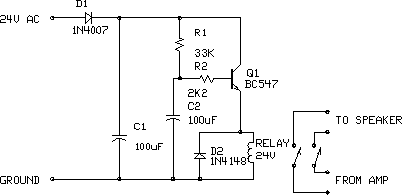
Audio Amplifier Output Relay Delay
This circuit is designed for an audio amplifier project to control the speaker output relay. Its primary function is to activate the relay that connects the speaker output to the amplifier after a delay of approximately 5 seconds following power-up,...
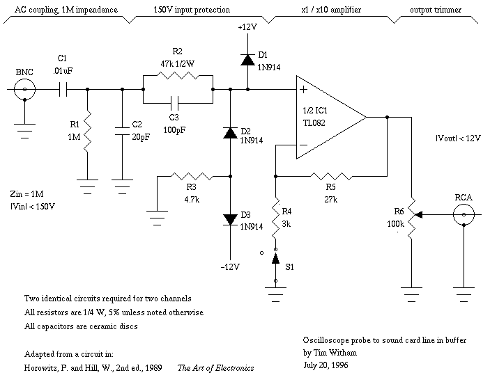
Capacitor in parallel with resistor on xoscope amplifier schematic
For capacitor C3, a 100pF capacitor is placed across resistor R2. The circuit functions similarly to previous configurations, although no explanation is provided. The purpose of this component may be self-evident to experienced users, but it may not be clear...
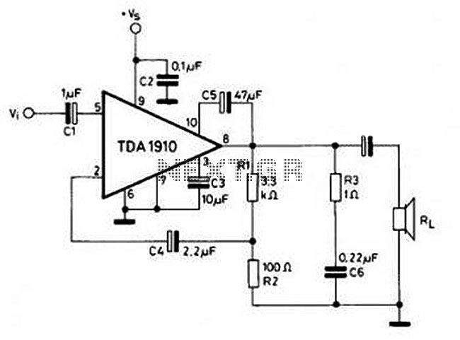
10W Audio Amplifier circuit based on TDA1910
This circuit is simple and inexpensive, which is its primary advantage. Although the output power is not high, the audio quality is good due to the TDA1910's low noise characteristics. This circuit is suitable for use as a student project.
The...
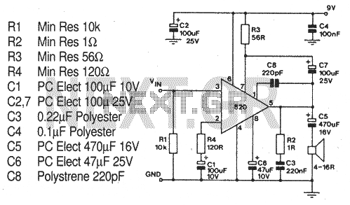
TBA820 Amplifier
A very useful audio amp in an 8-pin DIL package. The IC features a very low minimum working supply voltage of 3V, low quiescent current, good ripple rejection, no crossover distortion and low power dissipation. More: Maximum supply voltages is...
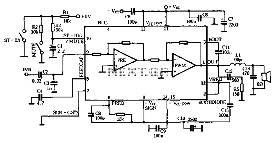
25W single-chip audio Class D amplifier IC-TDA7482
The PWM Class D audio amplifier has been the subject of exploration and reporting for over half a century. This technology is particularly attractive due to its high output efficiency, typically exceeding 85 to 90%. High output efficiency is especially...
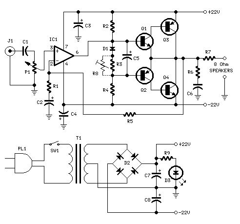
18W Audio Amplifier
18W Audio Amplifier. High-quality, very simple unit—no need for a preamplifier. Circuit diagram: Amplifier parts: P1 = 22K Log Potentiometer.
The 18W audio amplifier is designed to deliver high-quality sound amplification in a straightforward configuration, eliminating the need for a preamplifier...
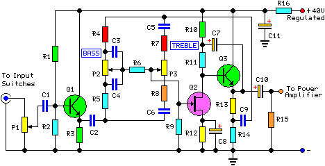
30 Watt Audio Power Amplifier
This project involved the design of an audio amplifier capable of delivering substantial output power with minimal component count while maintaining high quality. The power amplifier section utilizes three transistors along with a few resistors and capacitors in a shunt...
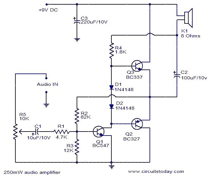
250mW audio amplifier
This is a simple three-transistor audio amplifier circuit capable of delivering 250 mW to an 8-ohm speaker. Complementary transistors BC337 and BC227 (Q3 and Q2) are utilized as the output pair, while transistor Q1 (BC547) functions as the preamplifier. The...
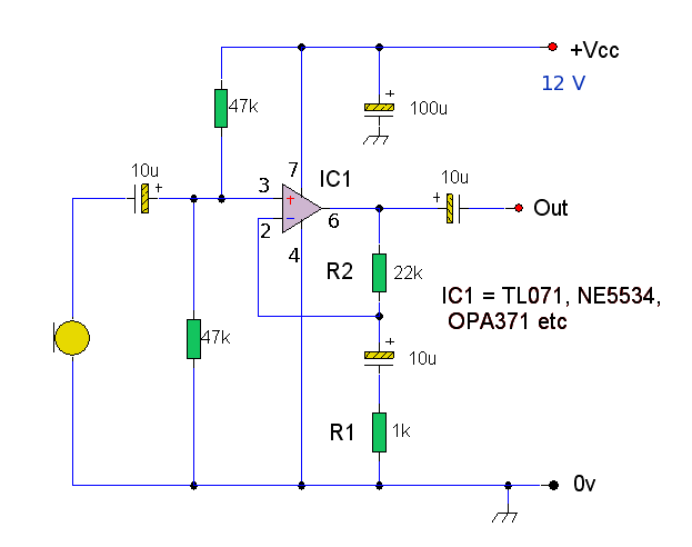
Op-Amp Microphone Preamp
A high-quality microphone preamplifier utilizing a single power supply, suitable for both dynamic and electret microphones. The operational amplifier (op-amp) employed can be any low-noise, high-performance type, such as the NE5534, TL071, or OPA 371. The schematic illustrates the configuration...