


Using kd-28 to do the voice switch circuit diagram
#voice-activated switch
#microphone
#amplifier
#audio signal
#control signal
#KD-28
#sound detection
#practical circuit
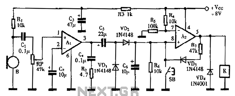
Description: A practical voice-activated switch is presented. An A1 amplifier is connected to a conventional microphone (B) that picks up the audio control signal, which is then amplified. After amplification, the signal passes through components C5, VD1, and VD2, forming a voltage doubler rectifier to charge capacitor C6. When the voice signal reaches a sufficient level, the charging voltage at pin 7 becomes high, activating the A2 amplifier. The output from A2 energizes relay K, closing its normally open contact and powering the connected appliances. Resistor R7 and diode VD3 provide self-locking for amplifier A2, ensuring that the output remains high at pin 5 and keeping the relay in an activated state. The release button (SB) is pressed to set pin 8 of A2 low, causing a flip in the output at pin 5 to low, which releases relay K. A potentiometer (RP) is included to adjust the sensitivity of the voice circuit. It is essential to select relay K with a rated voltage lower than the supply voltage Vcc by approximately 2V.
The voice-activated switch circuit utilizes an A1 amplifier configured to enhance audio signals captured by a microphone. The microphone (B) serves as the input transducer, converting sound waves into electrical signals, which are then amplified by A1. The amplified output is processed through a voltage doubler circuit, consisting of capacitors and diodes (C5, VD1, and VD2). This configuration effectively increases the voltage level, allowing capacitor C6 to store sufficient charge when the input audio signal exceeds a predetermined threshold.
The A2 amplifier operates as a comparator, where pin 7 receives the voltage from capacitor C6. Once the voltage surpasses a specific level, it triggers the output at pin 5 to go high, energizing relay K. This relay acts as a switch for external appliances, closing its normally open contacts to provide power. The inclusion of resistor R7 and diode VD3 creates a feedback loop that maintains the output of A2 high, keeping the relay energized even after the initial voice signal has ceased.
The circuit incorporates a manual release mechanism via button SB. When pressed, this button pulls pin 8 of A2 low, causing the output at pin 5 to drop, which subsequently deactivates relay K. This feature allows for manual control of the connected devices, ensuring they can be turned off when desired.
To fine-tune the sensitivity of the microphone and the overall responsiveness of the circuit to voice commands, a potentiometer (RP) is provided. Adjusting this component modifies the threshold at which the A2 amplifier responds to incoming audio signals.
When selecting relay K, it is critical to ensure that its rated operating voltage is approximately 2V lower than the supply voltage (Vcc) to prevent potential damage and ensure reliable operation. This design consideration is essential for maintaining the longevity and functionality of the voice-activated switch system. As shown is a practical voice-activated switch, A1 amplifier connected as a conventional microphone B picked up the audio control signal is amplified. After the amplified signa l through C5, VD1, VD2 voltage doubler rectifier to charge the capacitor C6, when the voice signal is sufficiently large, the charging voltage of 7 feet high and A2 level, then use similar op amp amplifier A2 output high relay K is energized, its normally open contact closure turned the accused appliances. R7 and VD3 amplifier A2 self-locking, so that A2 is always 5 feet high output, ensure attracted state relay.
SB is the release button, when pressed SB, 8 feet to the A2 input low, A2 flip, 5-pin output low, the relay K release. Potentiometer RP used to adjust the sensitivity level of the voice circuit. In the selection of the relay K work should pay attention to their rated voltage should be lower than the supply voltage Vcc of about about 2V.
The voice-activated switch circuit utilizes an A1 amplifier configured to enhance audio signals captured by a microphone. The microphone (B) serves as the input transducer, converting sound waves into electrical signals, which are then amplified by A1. The amplified output is processed through a voltage doubler circuit, consisting of capacitors and diodes (C5, VD1, and VD2). This configuration effectively increases the voltage level, allowing capacitor C6 to store sufficient charge when the input audio signal exceeds a predetermined threshold.
The A2 amplifier operates as a comparator, where pin 7 receives the voltage from capacitor C6. Once the voltage surpasses a specific level, it triggers the output at pin 5 to go high, energizing relay K. This relay acts as a switch for external appliances, closing its normally open contacts to provide power. The inclusion of resistor R7 and diode VD3 creates a feedback loop that maintains the output of A2 high, keeping the relay energized even after the initial voice signal has ceased.
The circuit incorporates a manual release mechanism via button SB. When pressed, this button pulls pin 8 of A2 low, causing the output at pin 5 to drop, which subsequently deactivates relay K. This feature allows for manual control of the connected devices, ensuring they can be turned off when desired.
To fine-tune the sensitivity of the microphone and the overall responsiveness of the circuit to voice commands, a potentiometer (RP) is provided. Adjusting this component modifies the threshold at which the A2 amplifier responds to incoming audio signals.
When selecting relay K, it is critical to ensure that its rated operating voltage is approximately 2V lower than the supply voltage (Vcc) to prevent potential damage and ensure reliable operation. This design consideration is essential for maintaining the longevity and functionality of the voice-activated switch system. As shown is a practical voice-activated switch, A1 amplifier connected as a conventional microphone B picked up the audio control signal is amplified. After the amplified signa l through C5, VD1, VD2 voltage doubler rectifier to charge the capacitor C6, when the voice signal is sufficiently large, the charging voltage of 7 feet high and A2 level, then use similar op amp amplifier A2 output high relay K is energized, its normally open contact closure turned the accused appliances. R7 and VD3 amplifier A2 self-locking, so that A2 is always 5 feet high output, ensure attracted state relay.
SB is the release button, when pressed SB, 8 feet to the A2 input low, A2 flip, 5-pin output low, the relay K release. Potentiometer RP used to adjust the sensitivity level of the voice circuit. In the selection of the relay K work should pay attention to their rated voltage should be lower than the supply voltage Vcc of about about 2V.
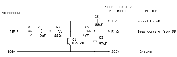
Sound Blaster Microphone Preamplifier
The circuit is fundamentally based on a well-tested simple microphone preamplifier design. A prototype of this circuit has been constructed and has demonstrated effective performance. The Sound Blaster soundcard series (SB16, SB32, AWE32, and AWE64) features a microphone input intended...
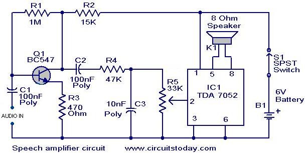
Speech amplifier circuit
This circuit can be housed within a box containing a speaker to create a convenient microphone amplifier. It is suitable for use by teachers, guides, lecturers, and others in crowded or noisy environments. The design is based on the audio...
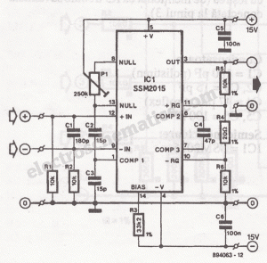
Low noise microphone preamplifier circuit
The microphone preamplifier circuit design presented in this schematic utilizes the SSM2015 produced by Precision Monolithics Inc. (PMI), which offers high amplification.
The SSM2015 is a low-noise, low-distortion integrated circuit designed specifically for microphone preamplification. It features a differential input stage...
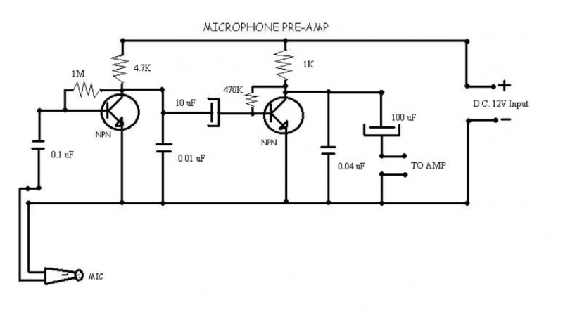
Microphone pre-amp
Cleaned Input:
Description: This circuit is used to give out a microphone preamp to an amplifier which will power the signal. The NPN transistors used are ECG123A. This circuit is also an older model to the one that now uses...
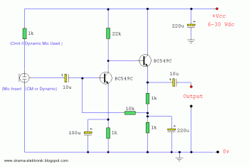
ecm mic preamplifier
Microphone amplifier schematics that can be utilized with either Electret Condenser Microphone (ECM) inserts or dynamic inserts, constructed with discrete components. The process of creating a PCB is straightforward. Begin by using PCB design software such as Eagle to create...
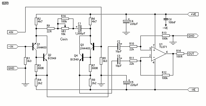
Balanced Microphone Preamp
The design consists of differential compound pairs of transistors with a common mode (floating) gain control connecting the emitters of the pair. The compound pairs of 2N4403 and BC549s are far more linear than any single transistor. The circuit is...
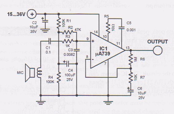
Low Voltage Microphone Preamplifier Circuit
This circuit is a low voltage microphone preamplifier that operates with a 1.5V power supply. It features a reference with a 500 kHz unity-gain bandwidth, functioning as a preamplifier with a gain of 100. The output from this stage is...
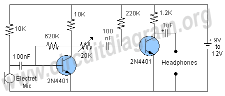
sensitive microphone circuit
The figure below illustrates a schematic of a highly sensitive microphone circuit designed to amplify faint sounds from a distance. The circuit exhibits significant sensitivity and offers substantial gain to weak audio signals.
The microphone circuit typically consists of several key...
Stereo audio power amplifier circuit using TDA2822
Circuit stereo TDA2822 audio power amplifier circuit schematics. In this series, the TDA2822M IC is utilized as the primary amplifier. Additionally, alternatives such as KA2209 and NJM2073 can also be employed.
The TDA2822 audio power amplifier circuit is designed to provide...