


Voice bandpass circuit diagram
#bandpass filter
#8 ohm speaker
#communication receiver
#voice transmission
#interference suppression
#low impedance
#audio circuit
#signal processing
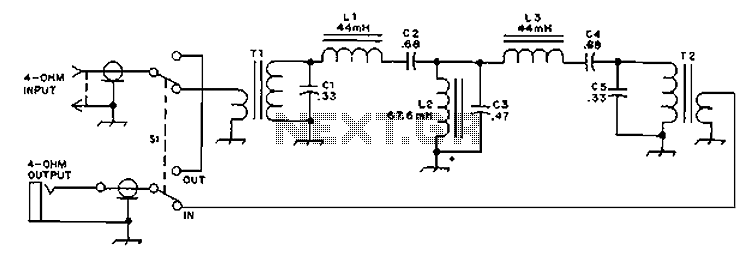
Description: The circuit provides an 8-ohm output for connecting communication receivers and low-impedance speakers or headphones, featuring harmful interference suppression for continuous random voice transmission. The passband ranges from 55 to 2530 Hz with a 3 dB bandwidth. Inductors L1 and L3 are rated at 4 mH, while inductor L2 is rated at 88 mH.
The circuit is designed to facilitate audio signal transmission while ensuring compatibility with various low-impedance audio devices. The 8-ohm output is particularly suited for communication receivers, enabling effective audio delivery to both speakers and headphones. The inclusion of interference suppression mechanisms is critical in maintaining audio clarity and preventing degradation of the transmitted signal from external noise sources.
The specified passband of 55 to 2530 Hz indicates the frequency range within which the circuit operates effectively, making it suitable for a wide array of audio frequencies typically encountered in voice communication. The 3 dB bandwidth implies that the circuit will maintain a relatively flat frequency response within this range, ensuring minimal signal loss and distortion.
Inductors L1 and L3, each rated at 4 mH, and inductor L2, rated at 88 mH, play a vital role in the circuit's filtering capabilities. The inductors are configured to manage the impedance and enhance the overall performance of the audio transmission. The lower inductance values of L1 and L3 may be utilized for high-frequency filtering, while the higher inductance of L2 can be responsible for low-frequency response, allowing for a balanced audio output.
Overall, this circuit design is optimized for efficient audio transmission in communication applications, providing a robust solution for connecting to various audio output devices while minimizing interference and maintaining audio integrity across the specified frequency range.8 ohm output for connecting communication receivers and 8 ohm speaker or low impedance phones, harmful interference suppression continuous random voice transmission. Passband 3 55 to 2530Hz, 3dB. L1 and L3 are 4amH the ring. L2 is 88mH the ring.
The circuit is designed to facilitate audio signal transmission while ensuring compatibility with various low-impedance audio devices. The 8-ohm output is particularly suited for communication receivers, enabling effective audio delivery to both speakers and headphones. The inclusion of interference suppression mechanisms is critical in maintaining audio clarity and preventing degradation of the transmitted signal from external noise sources.
The specified passband of 55 to 2530 Hz indicates the frequency range within which the circuit operates effectively, making it suitable for a wide array of audio frequencies typically encountered in voice communication. The 3 dB bandwidth implies that the circuit will maintain a relatively flat frequency response within this range, ensuring minimal signal loss and distortion.
Inductors L1 and L3, each rated at 4 mH, and inductor L2, rated at 88 mH, play a vital role in the circuit's filtering capabilities. The inductors are configured to manage the impedance and enhance the overall performance of the audio transmission. The lower inductance values of L1 and L3 may be utilized for high-frequency filtering, while the higher inductance of L2 can be responsible for low-frequency response, allowing for a balanced audio output.
Overall, this circuit design is optimized for efficient audio transmission in communication applications, providing a robust solution for connecting to various audio output devices while minimizing interference and maintaining audio integrity across the specified frequency range.8 ohm output for connecting communication receivers and 8 ohm speaker or low impedance phones, harmful interference suppression continuous random voice transmission. Passband 3 55 to 2530Hz, 3dB. L1 and L3 are 4amH the ring. L2 is 88mH the ring.
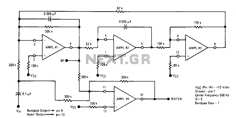
Bandpass and notch filter
The Quad op-amp MC4301 is employed to configure a filter that eliminates a specific frequency, outputting the notched frequency at the BP terminal. This is particularly useful in communication or measurement setups. By selecting appropriate components, filters capable of targeting...

Active Second-Order Bandpass Filter Circuit
This filter circuit, which utilizes the LM1458 or a similar operational amplifier, has a frequency response ranging from 300 Hz to 3.4 kHz, exhibiting a roll-off of 12 dB per octave outside the passband. Section A serves as the high-pass...
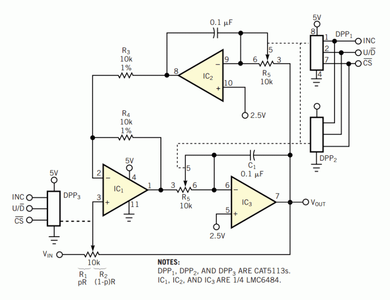
DPPs program key parameters of bandpass filter
The three-amplifier implementation of the state-variable filter in Figure 1 provides for second-order bandpass, highpass, and lowpass responses. The strength of the circuit, however, is in the bandpass response (VOUT/VIN), in which it's easy to achieve high gain (G) and...
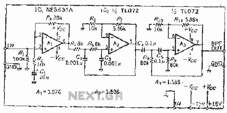
Measuring SN audio bandpass filter circuit
The filter incorporates a zoom function, with a front satin amplifier magnification calculated as d = 10/2.515 = 3.97, which results in a total beam compared to a 10 times magnification. The low-pass filter parameters are specified as a cutoff...
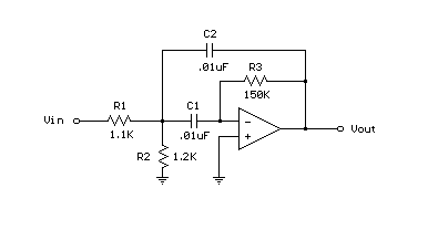
Bandpass Filter schematic
A bandpass filter passes a range of frequencies while rejecting frequencies outside the upper and lower limits of the passband. The range of frequencies to be passed is called the passband and extends from a point below the center frequency...
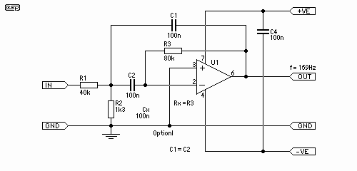
Feedback Bandpass Filter
These filters are useful for equalisation, analysis and other tasks such as the Sound to Light converter (Project 62) or even a fully functional Vocoder. For those who have not heard of the vocoder, it is a device that takes...
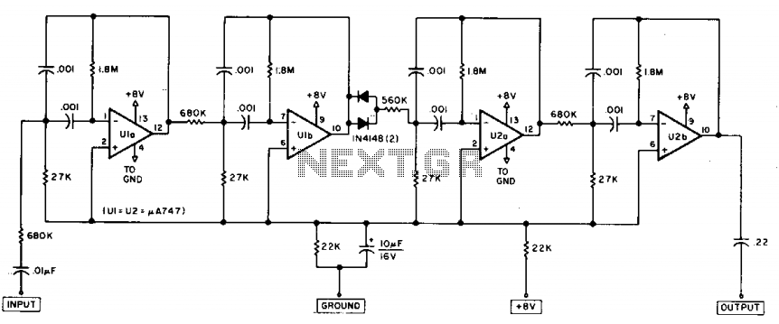
Razor-sharp CW filter
The circuit consists of four stages of active bandpass filtering provided by two type-µ integrated-circuit dual op-amps and includes a simple threshold detector (diodes D1 and D2) between stages 2 and 3 to reduce low-level background noise. Each of the...
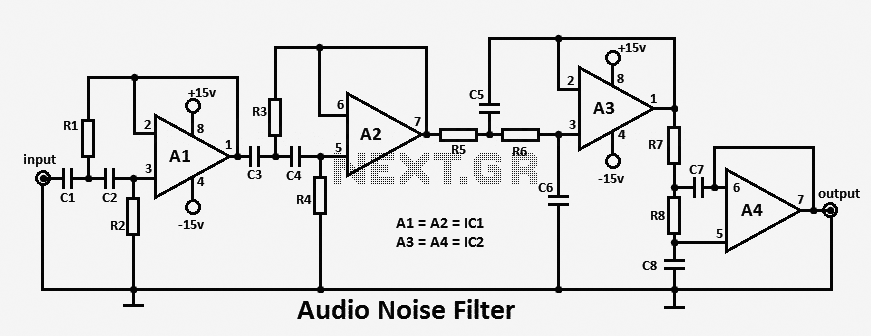
Audio Noise Filter circuit
This audio noise filter circuit functions as a bandpass filter specifically designed for the audio frequency range. It effectively filters out unwanted signals that fall below or above the desired audio frequencies. The circuit comprises two filters: a low-pass filter...
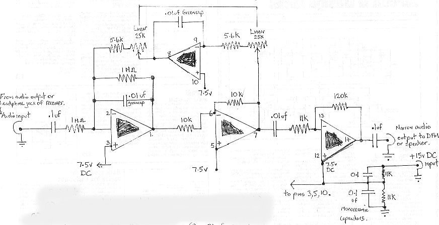
audio bandpass filter
The audio bandpass filter described is beneficial for amplifying and filtering weak AM TV video carriers. For instance, a digital frequency audio multimeter (DFM) may lack sufficient input sensitivity for measuring extremely weak single sideband (SSB) TV video audio signals....