


Voice changer circuit diagram electronic projects using RTS0072B

Description: This voice changer circuit diagram is an electronic project developed using the RTS0072B single-chip CMOS LSI, specifically designed for voice-changing applications. It can transpose or distort one voice into another by encoding the input audio signals at normal speed and transmitting the output audio signals at an unusual speed. The voice changing effect is achieved by sampling the input audio signals into digital signals and rearranging these digital signals to produce a different voice from the user's normal voice. The circuit design is straightforward and requires only a few external electronic components. The circuit must be powered by a DC power supply that provides a fixed output voltage between 3 and 5 volts. In this project, a 9-volt DC power supply is utilized because the circuit employs an LM386 audio amplifier IC to amplify the output signal.
The voice changer circuit utilizes the RTS0072B CMOS LSI as the core component, which is tailored for voice manipulation tasks. This integrated circuit allows for easy implementation of voice modulation features, including pitch shifting and voice distortion. The audio input is captured through a microphone, which converts sound waves into electrical signals. These signals are then processed by the RTS0072B, where they are sampled and converted into digital format.
The digital signal processing involves encoding the input audio, which is then manipulated to achieve the desired voice effect. The output is generated at a different speed, resulting in a unique voice characteristic that can be used for various applications such as entertainment, games, or privacy.
The circuit requires minimal external components, which may include resistors, capacitors, and a few connectors. The simplicity of the design makes it accessible for hobbyists and those new to electronics. Powering the circuit with a DC supply between 3 to 5 volts is crucial for the operation of the RTS0072B. However, the use of a 9-volt DC power supply in this project is necessary to ensure adequate performance of the LM386 audio amplifier, which boosts the output audio signal to a suitable volume for playback through speakers or headphones.
Overall, this voice changer circuit is an efficient and straightforward project that demonstrates the principles of audio processing and amplification, making it an excellent choice for educational purposes or as a fun DIY project.This voice changer circuit diagram electronic project is designed using the RTS0072B single chip CMOS LSI designed for voice changer applications, which can transpose or distort one voice into another voice by encoding the input audio signals in normal speed and transmit the output audio signals with unusual speed. Voice changer is accomplished b y sampling the input audio signals into digital signals and re-arranges the digital signals to generate different voice from the user normal voice. This circuit design project is very simple and require few external electronic parts. Circuit must be powered from a DC power supply circuit that will provide a fixed output voltage between 3 and 5 volts.
As you can see in this project is used a 9 volts DC power supply, because this circuit uses a LM386 audio amplifier IC that will amplify the output signal.
The voice changer circuit utilizes the RTS0072B CMOS LSI as the core component, which is tailored for voice manipulation tasks. This integrated circuit allows for easy implementation of voice modulation features, including pitch shifting and voice distortion. The audio input is captured through a microphone, which converts sound waves into electrical signals. These signals are then processed by the RTS0072B, where they are sampled and converted into digital format.
The digital signal processing involves encoding the input audio, which is then manipulated to achieve the desired voice effect. The output is generated at a different speed, resulting in a unique voice characteristic that can be used for various applications such as entertainment, games, or privacy.
The circuit requires minimal external components, which may include resistors, capacitors, and a few connectors. The simplicity of the design makes it accessible for hobbyists and those new to electronics. Powering the circuit with a DC supply between 3 to 5 volts is crucial for the operation of the RTS0072B. However, the use of a 9-volt DC power supply in this project is necessary to ensure adequate performance of the LM386 audio amplifier, which boosts the output audio signal to a suitable volume for playback through speakers or headphones.
Overall, this voice changer circuit is an efficient and straightforward project that demonstrates the principles of audio processing and amplification, making it an excellent choice for educational purposes or as a fun DIY project.This voice changer circuit diagram electronic project is designed using the RTS0072B single chip CMOS LSI designed for voice changer applications, which can transpose or distort one voice into another voice by encoding the input audio signals in normal speed and transmit the output audio signals with unusual speed. Voice changer is accomplished b y sampling the input audio signals into digital signals and re-arranges the digital signals to generate different voice from the user normal voice. This circuit design project is very simple and require few external electronic parts. Circuit must be powered from a DC power supply circuit that will provide a fixed output voltage between 3 and 5 volts.
As you can see in this project is used a 9 volts DC power supply, because this circuit uses a LM386 audio amplifier IC that will amplify the output signal.
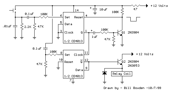
CD4013 Push Button CMOS Toggle Flip Flop
The circuit utilizes a CMOS dual D flip-flop (CD4013) to toggle a relay or other load using a momentary push button. Multiple push buttons can be connected in parallel to control the relay from various locations. A high signal from...
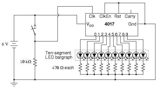
LED sequencer
The model 4017 integrated circuit is a CMOS counter with ten output terminals. One of these ten terminals will be in a "high" state at any given time, with all others being "low," giving a "one-of-ten" output sequence. If low-to-high...

4093 Cmos Vfo Circuit
Two gates of a Quad 4093 are utilized in an astable multivibrator configuration. CI is a three-gang 365 pF variable capacitor with its sections connected in parallel. Additionally, S3 and S4 serve to switch in optional extra capacitors.
The described circuit...
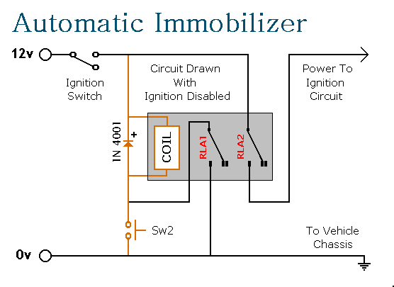
Cmos Based Vehicle Anti-Theft Alarm
This circuit features automatic exit and entry delays, an optional instant alarm zone, an optional intermittent siren output, and an automatic reset. By adding external relays, the vehicle can be immobilized and the lights can be flashed. The alarm is...
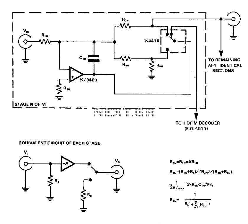
Audio input selector circuit (4416 CMOS)
CMOS switches are utilized to select entries in audio circuits. While these switches can introduce unacceptable levels of distortion, incorporating them into the feedback network of an operational amplifier (op amp) can effectively minimize this distortion. The circuit employs a...
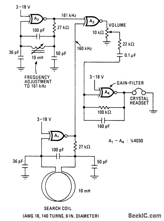
MICROPOWER METAL DETECTOR
This battery-powered metal detector utilizes four exclusive-OR gates found in the 4030 CMOS integrated circuit. The gates are configured as twin oscillators, with a search coil acting as the inductance element in one of the oscillators. When the coil approaches...
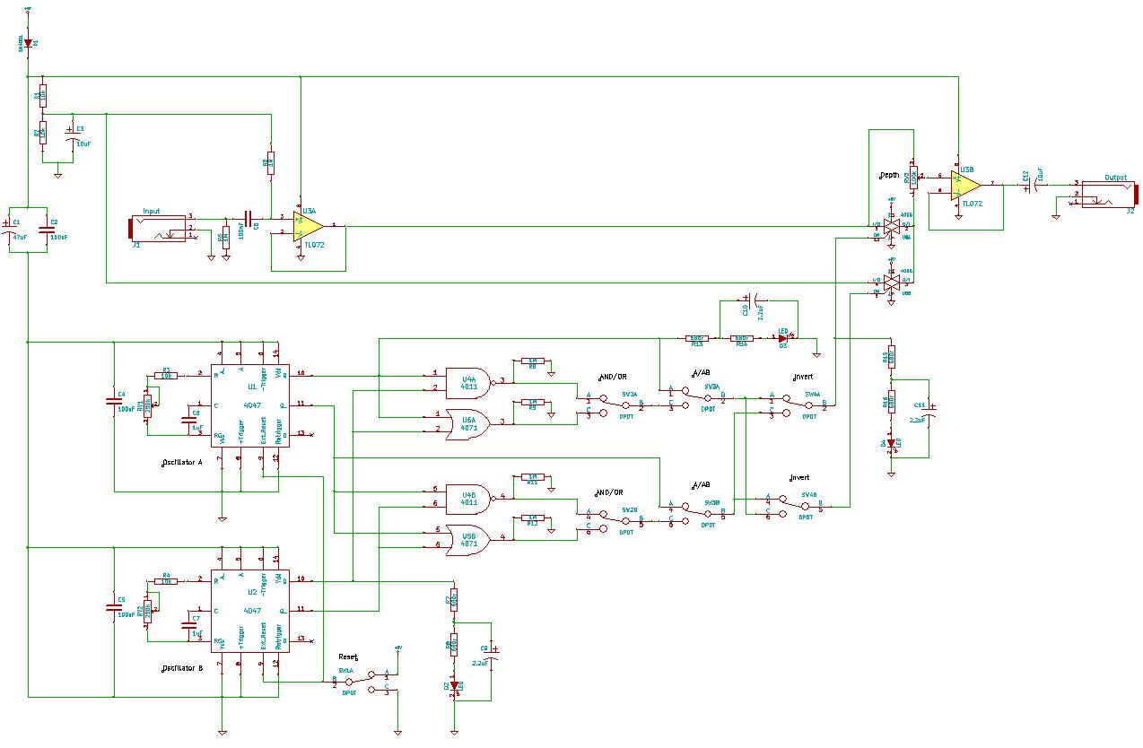
4047/4066 audio slicer
You need to connect pins 1 and 13 of the 4053 to the virtual ground rail (top of C4), not the circuit's 0V rail.
The CD4053 is a triple 2-channel analog multiplexer/demultiplexer integrated circuit, widely used for routing analog signals...
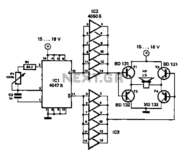
Simple circuit diagram repellent
A low-cost and straightforward repellent circuit can be utilized for deterring rats, mice, and other animals, as illustrated in the electronic figure below. The circuit employs a CMOS integrated circuit of type 4047, which functions as a relaxation oscillator. Its...
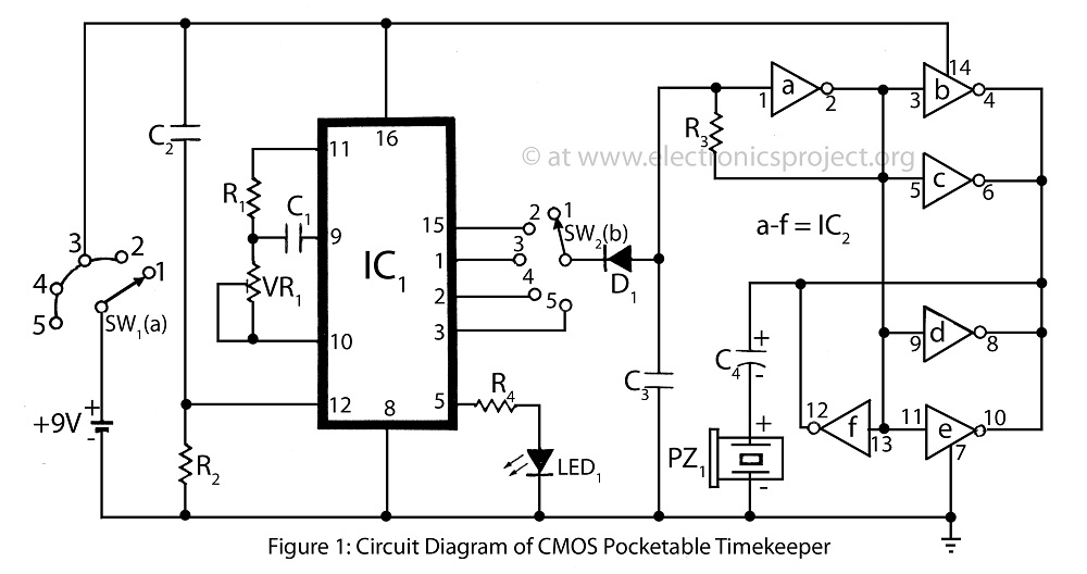
CMOS Pocketable Timekeeper
The CMOS Pocketable Timekeeper is a compact timekeeping circuit designed for portability. This circuit diagram illustrates the functionality of the CMOS Pocketable Timekeeper along with various advanced timer projects and electronic applications.
The CMOS Pocketable Timekeeper circuit utilizes complementary metal-oxide-semiconductor (CMOS)...