


Voice Disguiser Circuit
#voice disguiser
#audio amplifier
#balanced modulator
#low-pass filter
#oscillator
#microphone
#transistor
#operational amplifier
#signal processing
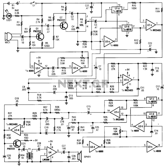
Description: A complete schematic diagram of the voice disguiser is presented. Microphone MIC1 captures the voice signal and transmits it to an audio amplifier, which consists of Q1 and Q2, along with several supporting components. This amplifier features a low-pass gain response that restricts the voice frequencies to 5 kHz or lower. The voice signal is subsequently directed to the input of the first balanced modulator, comprising U1-a, U1-b, U2-a, and U3-a. The output from the first 4-kHz oscillator, constructed around U3-f and U3-e, is supplied to the carrier input of the first modulator. The oscillator's frequency is regulated by the setting of potentiometer R13. The modulator produces a double-sideband suppressed-carrier signal centered on 4 kHz, which is then processed by the first 5-kHz low-pass filter, formed by U2-b, to eliminate the upper-sideband signals.
At this stage, the voice frequency spectrum is inverted (e.g., lower frequencies become higher, and vice versa), rendering the voice signal entirely unintelligible. The output from the first low-pass filter is sent to a second modulator, composed of U1-c, U1-d, and U3-b, where it undergoes frequency modulation using the output from the second carrier oscillator, made up of U3-c and U3-d; the frequency of this second oscillator is adjusted by potentiometer R36. The output of the second modulator is filtered by a second low-pass filter, consisting of U2-d and several supporting components, and is subsequently amplified by Q3. The voice output signal from Q3 is then transmitted to U4 (an LM386 low-voltage audio power amplifier) through an impedance-matching transformer, T1. The output from U4 is used to drive SPKR1 (an 8-ohm speaker). During operation, if both carrier oscillators are set to the same frequency, the voice signal from the speaker replicates the input signal from the microphone. However, varying the frequency of the second oscillator (via R36) alters the output voice signal's frequency, causing the reproduced voice to sound either higher or lower in pitch than normal.
The voice disguiser circuit is designed to obscure the original voice signal effectively. The use of a microphone (MIC1) initiates the process by capturing the audio input, which is then amplified to ensure sufficient signal strength for further processing. The low-pass filter integrated within the amplifier circuit limits the frequency range to eliminate any high-frequency noise that may interfere with the modulation process.
The balanced modulator configuration is crucial for creating the double-sideband suppressed-carrier signal, which is essential for the subsequent frequency inversion. By utilizing two oscillators, the circuit allows for the manipulation of the output signal's frequency, providing flexibility in voice modulation. The second modulator further enhances the disguise effect by applying frequency modulation to the already inverted signal.
The final amplification stage, using the LM386, is tailored for low-voltage applications, making it suitable for battery-powered or portable devices. The impedance-matching transformer ensures proper coupling between the amplifier and the speaker, optimizing the sound output. The design allows for real-time adjustments of the modulation frequency, enabling users to customize the pitch of the voice output, thereby enhancing the versatility of the voice disguiser. A complete schematic diagram of the voice disguiser is shown. Microphone MIC1 picks up the voice signal and feeds it to an audio amplifier, consisting of Ql and Q2, and a few support components. The amplifier has a low-pass gain response that limits the voice frequencies to 5 kHz or lower. The voice signal is then fed to the input of the first, balanced modulator, which is comprised of Ul-a, Ul-b, U2-a, and U3-a.
The output of the first 4-kHz oscillator, built around U3-f and U3-e, is fed to the carrier input of the first, modulator. The frequency of the first oscillator is controlled by the setting of potentiometer R13. The modulator outputa double-sideband suppressed-carrier signal centered on 4 kHzis then filtered by the first 5-kHz low-pass filter, formed by U2-b, which eliminates the upper-sideband signals.
At this point, the voice frequency spectrum is inverted (e.g., the frequencies that were low now become high, and vice versa), making the voice signal completely unintelligible. The output of the first low-pass filter is fed to a second modulator formed by Ul-c, Ul-d, and U3-b, where it is frequency modulated with the output of the second carrier oscillator, comprised of U3-c and U3-d; the frequency of the second oscillator is controlled by potentiometer R36.
The output of the second modulator is filtered by the second low-pass filter, which consists of U2-d and few support components, and amplified by Q3. The voice output signal from Q3 is fed to U4 (an LM386 low-voltage, audio-power amplifier) through an impedance-matching transformer, Tl.
The output of U4 is then used to drive SPKR1 (ari 8- speaker). In operation, if both carrier oscillators are set to the same frequency, the voice signal from the speaker will be an exact duplicate of the input signal from the microphone. However, if the frequency of the second oscillator is varied (via R36), the output voice signal also shifts in frequency.
That makes the voice reproduced by the speaker sound higher- or lower-pitched than normal.
At this stage, the voice frequency spectrum is inverted (e.g., lower frequencies become higher, and vice versa), rendering the voice signal entirely unintelligible. The output from the first low-pass filter is sent to a second modulator, composed of U1-c, U1-d, and U3-b, where it undergoes frequency modulation using the output from the second carrier oscillator, made up of U3-c and U3-d; the frequency of this second oscillator is adjusted by potentiometer R36. The output of the second modulator is filtered by a second low-pass filter, consisting of U2-d and several supporting components, and is subsequently amplified by Q3. The voice output signal from Q3 is then transmitted to U4 (an LM386 low-voltage audio power amplifier) through an impedance-matching transformer, T1. The output from U4 is used to drive SPKR1 (an 8-ohm speaker). During operation, if both carrier oscillators are set to the same frequency, the voice signal from the speaker replicates the input signal from the microphone. However, varying the frequency of the second oscillator (via R36) alters the output voice signal's frequency, causing the reproduced voice to sound either higher or lower in pitch than normal.
The voice disguiser circuit is designed to obscure the original voice signal effectively. The use of a microphone (MIC1) initiates the process by capturing the audio input, which is then amplified to ensure sufficient signal strength for further processing. The low-pass filter integrated within the amplifier circuit limits the frequency range to eliminate any high-frequency noise that may interfere with the modulation process.
The balanced modulator configuration is crucial for creating the double-sideband suppressed-carrier signal, which is essential for the subsequent frequency inversion. By utilizing two oscillators, the circuit allows for the manipulation of the output signal's frequency, providing flexibility in voice modulation. The second modulator further enhances the disguise effect by applying frequency modulation to the already inverted signal.
The final amplification stage, using the LM386, is tailored for low-voltage applications, making it suitable for battery-powered or portable devices. The impedance-matching transformer ensures proper coupling between the amplifier and the speaker, optimizing the sound output. The design allows for real-time adjustments of the modulation frequency, enabling users to customize the pitch of the voice output, thereby enhancing the versatility of the voice disguiser. A complete schematic diagram of the voice disguiser is shown. Microphone MIC1 picks up the voice signal and feeds it to an audio amplifier, consisting of Ql and Q2, and a few support components. The amplifier has a low-pass gain response that limits the voice frequencies to 5 kHz or lower. The voice signal is then fed to the input of the first, balanced modulator, which is comprised of Ul-a, Ul-b, U2-a, and U3-a.
The output of the first 4-kHz oscillator, built around U3-f and U3-e, is fed to the carrier input of the first, modulator. The frequency of the first oscillator is controlled by the setting of potentiometer R13. The modulator outputa double-sideband suppressed-carrier signal centered on 4 kHzis then filtered by the first 5-kHz low-pass filter, formed by U2-b, which eliminates the upper-sideband signals.
At this point, the voice frequency spectrum is inverted (e.g., the frequencies that were low now become high, and vice versa), making the voice signal completely unintelligible. The output of the first low-pass filter is fed to a second modulator formed by Ul-c, Ul-d, and U3-b, where it is frequency modulated with the output of the second carrier oscillator, comprised of U3-c and U3-d; the frequency of the second oscillator is controlled by potentiometer R36.
The output of the second modulator is filtered by the second low-pass filter, which consists of U2-d and few support components, and amplified by Q3. The voice output signal from Q3 is fed to U4 (an LM386 low-voltage, audio-power amplifier) through an impedance-matching transformer, Tl.
The output of U4 is then used to drive SPKR1 (ari 8- speaker). In operation, if both carrier oscillators are set to the same frequency, the voice signal from the speaker will be an exact duplicate of the input signal from the microphone. However, if the frequency of the second oscillator is varied (via R36), the output voice signal also shifts in frequency.
That makes the voice reproduced by the speaker sound higher- or lower-pitched than normal.
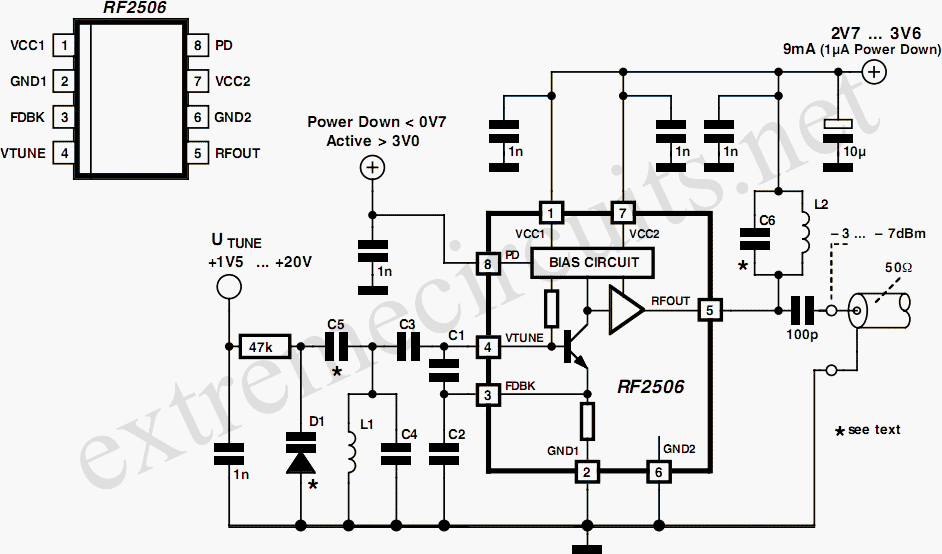
10 to 1000 MHz Oscillator circuit with RF2506
Today, it is no longer necessary to use discrete components for constructing oscillators. Many manufacturers now offer ready-made voltage-controlled oscillator (VCO) integrated circuits (ICs) that require only a few external components to determine the frequency. An example of such an...
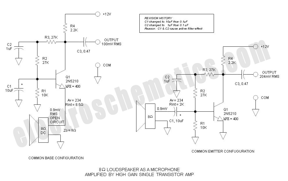
Common Base vs Common Emitter - Single Transistor Amplifier
Single Transistor Amplifier Revisited Part 3, Common Base vs Common Emitter Configuration, Update One nagging question that I have long had is this: How do...
The single transistor amplifier is a fundamental building block in electronic circuits, and its configurations—common base...

Local Oscillator For Double Balanced Mixers Circuit
This circuit includes an amplifier designed to deliver +10 dBm to an SBL series (Mini-Circuits) or a similar type of doubly-balanced mixer assembly. The circuit parameters are specified for 80 to 90 MHz crystals, although the values of the oscillator...
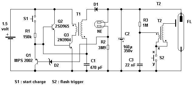
Camera flash circuit
A simple transistor generator and transformer converts a 1.5V battery voltage to several hundred volts. This high voltage current then passes through a diode, which rectifies the current to DC. This DC current is stored in a relatively large capacitor....
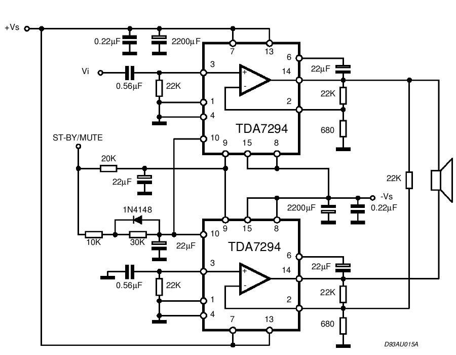
TDA Amplifier Circuits
The TDA integrated circuit series is highly regarded and widely utilized in amplifier designs and projects. TDA audio amplifier circuits are primarily produced by Philips and SGS-THOMSON. The most commonly used ICs include the TDA2030 and TDA2003 for small audio...
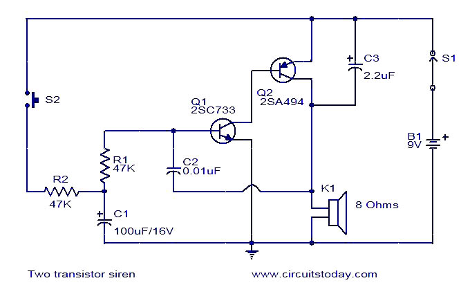
Two transistor siren
The circuit diagram illustrates a simple two-transistor alarm circuit powered by a 9V PP3 battery. In this configuration, the two transistors are arranged to create an oscillator. The frequency of the oscillator increases when switch S2 is pressed and decreases...
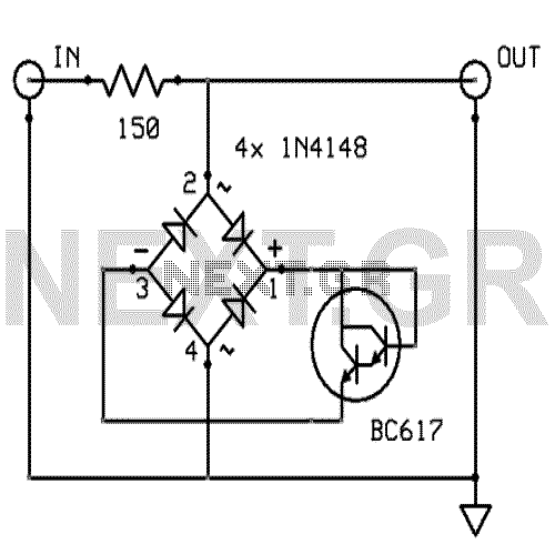
Amplifier input signal overdrive auto-protection
That circuit protects the overdriven signals going into an amplifier. Instead of a zener diode, we use a transistor. That way we ensure that the above the ordinary input voltages (1 volt r.m.s.) can be achieved without distortion. Also, the...
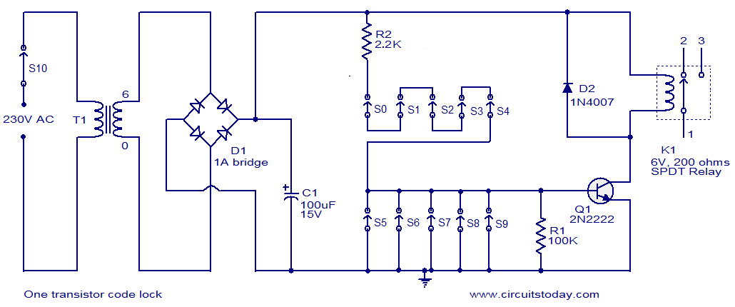
One transistor code lock
This is a simple electronic code lock circuit that can be easily constructed. The circuit consists of one transistor, a relay, and several passive components. Its simplicity does not compromise performance, and it functions effectively. The circuit operates as a...
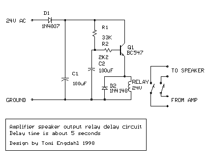
Audio amplifier output relay delay
This circuit was designed for an audio amplifier project to control the speaker output relay. Its primary function is to manage the relay that activates the speaker output in the audio amplifier, ensuring a delay of approximately 5 seconds after...