


Whistle to beep circuit
#whistle detection
#beep generator
#CD4049
#audio amplifier
#band pass filter
#microphone
#sound circuit
#CMOS inverter
#signal processing
#simple circuit
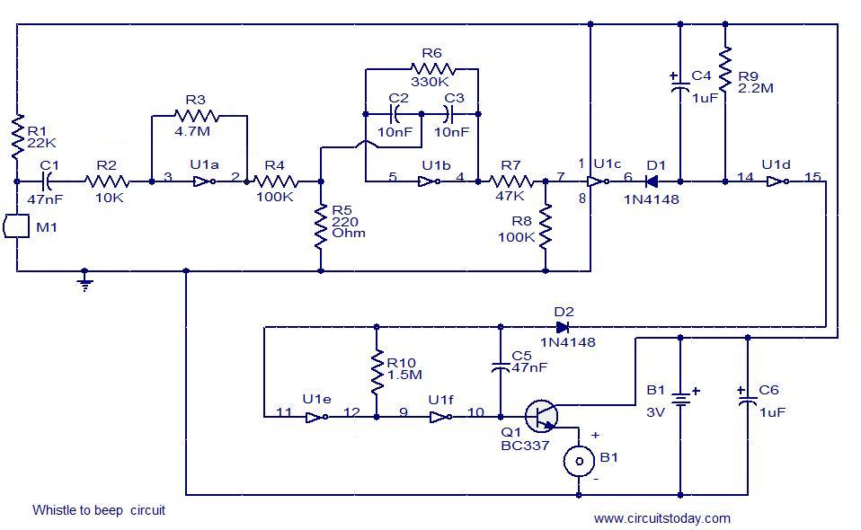
Description: This simple circuit produces a beeping sound that lasts for approximately 3 seconds whenever a whistle is made. The CMOS Hex inverter CD4049 serves as the core component of this circuit. Among the six inverters in the CD4049, U1a is configured as an audio amplifier, which amplifies the signal received from the microphone M1. U1b is arranged as a band-pass filter with a center frequency around 2 kHz. This filter is essential for allowing the frequency associated with the whistling sound to pass while suppressing other frequencies. Without this filter, the circuit could easily be falsely triggered. U1d is configured as a 3-second delay monostable multivibrator. The output from U1d drives the astable multivibrator formed by U1e and U1f, which operates at around 4 Hz. The combined effect results in an intermittent beeping sound lasting approximately 3 seconds. Transistor Q1 is employed to drive the buzzer B1.
The circuit utilizes a CMOS Hex inverter CD4049, which is a versatile component commonly used in various applications due to its low power consumption and high noise immunity. The microphone M1 acts as the input sensor, detecting the whistling sound. The audio amplifier configuration of U1a ensures that the weak signal from the microphone is sufficiently amplified to trigger subsequent stages of the circuit.
The band-pass filter designed with U1b is critical in isolating the desired frequency range. By focusing on the center frequency of around 2 kHz, the filter effectively allows whistling sounds to pass through while attenuating background noise and other irrelevant frequencies. This filtering capability is crucial for preventing false triggering, which could occur if the circuit responds to non-whistling sounds.
U1d, configured as a monostable multivibrator, introduces a time delay of 3 seconds. When activated by the amplified signal, it generates a single output pulse that lasts for the duration of the delay. This pulse then triggers the astable multivibrator formed by U1e and U1f, which produces a square wave output at approximately 4 Hz. This creates the intermittent beeping sound, as the astable multivibrator oscillates between its high and low states.
Transistor Q1 acts as a switch, controlled by the output from the monostable multivibrator. When Q1 is activated, it allows current to flow to the buzzer B1, generating the audible beep. The design of this circuit is straightforward yet effective, making it an excellent example of integrating basic electronic components to create a functional audio signaling device. This circuit can be further enhanced by incorporating additional features such as adjustable sensitivity or volume control to tailor its operation to specific applications.This simple circuit produces a beeping sound that lasts for around 3 seconds whenever you make a whistle. The CMOS Hex inverter CD4049 is the heart of this circuit. Out of the six inverters in CD4049, U1a is wired as an audio amplifier which amplifies the signal picked up by the microphone M1.
The U1b is wired as a band pass filter with center freq uency around 2KHz. The filter is necessary in order to pass the frequency corresponding to whistling sound and suppress all other frequencies. If the filter is not there, the circuit could easily get false triggered. U1d is wired as a 3S delay monostable multivibrator. The output U1d drives the astable multivibrator formed by U1e and U1f. The astable multivibrator is operating around 4Hz. The combined effect is a intermittent beeping sound that lasts for around 3S. Transistor Q1 is used to drive the buzzer B1.
The circuit utilizes a CMOS Hex inverter CD4049, which is a versatile component commonly used in various applications due to its low power consumption and high noise immunity. The microphone M1 acts as the input sensor, detecting the whistling sound. The audio amplifier configuration of U1a ensures that the weak signal from the microphone is sufficiently amplified to trigger subsequent stages of the circuit.
The band-pass filter designed with U1b is critical in isolating the desired frequency range. By focusing on the center frequency of around 2 kHz, the filter effectively allows whistling sounds to pass through while attenuating background noise and other irrelevant frequencies. This filtering capability is crucial for preventing false triggering, which could occur if the circuit responds to non-whistling sounds.
U1d, configured as a monostable multivibrator, introduces a time delay of 3 seconds. When activated by the amplified signal, it generates a single output pulse that lasts for the duration of the delay. This pulse then triggers the astable multivibrator formed by U1e and U1f, which produces a square wave output at approximately 4 Hz. This creates the intermittent beeping sound, as the astable multivibrator oscillates between its high and low states.
Transistor Q1 acts as a switch, controlled by the output from the monostable multivibrator. When Q1 is activated, it allows current to flow to the buzzer B1, generating the audible beep. The design of this circuit is straightforward yet effective, making it an excellent example of integrating basic electronic components to create a functional audio signaling device. This circuit can be further enhanced by incorporating additional features such as adjustable sensitivity or volume control to tailor its operation to specific applications.This simple circuit produces a beeping sound that lasts for around 3 seconds whenever you make a whistle. The CMOS Hex inverter CD4049 is the heart of this circuit. Out of the six inverters in CD4049, U1a is wired as an audio amplifier which amplifies the signal picked up by the microphone M1.
The U1b is wired as a band pass filter with center freq uency around 2KHz. The filter is necessary in order to pass the frequency corresponding to whistling sound and suppress all other frequencies. If the filter is not there, the circuit could easily get false triggered. U1d is wired as a 3S delay monostable multivibrator. The output U1d drives the astable multivibrator formed by U1e and U1f. The astable multivibrator is operating around 4Hz. The combined effect is a intermittent beeping sound that lasts for around 3S. Transistor Q1 is used to drive the buzzer B1.
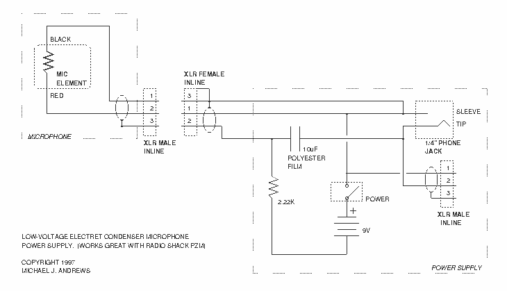
Pressure Zone Microphone (PZM) Modifications
After attempting to use this reportedly "pretty good" microphone in a variety of situations with some "pretty bad" results, I dissected the power supply and found the same audio transformer that’s in their 180-in-one project kits! This DAT-Heads Digest article...
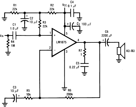
Circuit of power audio amplifier lm1875 20W
The LM1875 is a monolithic audio amplifier that provides very low distortion and high-quality performance for audio amplifier projects. The LM1875 delivers 20 watts into loads of 4 Ohms or 8 Ohms.
The LM1875 audio amplifier is designed for applications requiring...
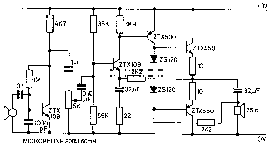
Microphone-amplifier
This circuit utilizes the ZTX450 and ZTX550 transistors configured in a push-pull output stage. The following measurements were recorded at maximum volume: Input: 0.4 mV rms, Output: 1.8 V rms, Voltage gain: 4500, Maximum output before distortion: 2.25 V rms,...
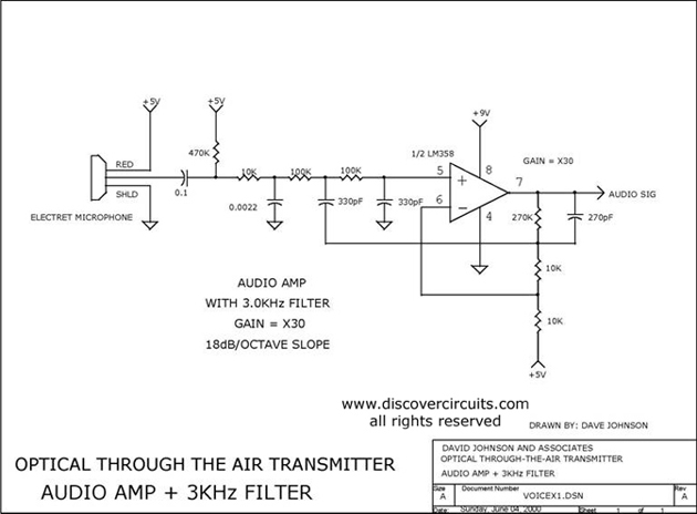
AUDIO AMP + 3KHz FILTER
Audio amplifier with a 3 kHz filter. This circuit serves as the audio amplification section for a complete optical transmitter. It amplifies and filters voice audio signals from an electret microphone.
The audio amplifier circuit is designed to enhance the weak...
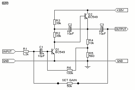
Low Noise Microphone Preamplifier
Cleaned Input: This is a design for a low noise microphone preamplifier, which is ideally suited to low impedance (600 Ohm nominal) microphones. One limitation is that it is not balanced, which is not a problem in a home recording...

2W Amplifier
Designed for self-powered 8, 4 & 2 Ohm loudspeakers. This amplifier was designed to be self-contained in a small loudspeaker box. It can be fed by Walkman, Mini-Disc, iPod and CD players, computers and similar devices fitted with line or...
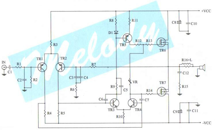
100 watt simple mosfet power amp
The schematic diagram of a 100-watt audio amplifier utilizing MOSFET technology. A comprehensive collection of electronic circuit diagrams is available, including a 100W RMS amplifier and a 0-30V stabilized variable power supply with current control.
The 100-watt audio amplifier schematic employs...
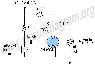
microphone preamp circuit
This schematic illustrates a highly sensitive microphone preamplifier circuit designed to amplify the gain of a microphone or enhance audio signals originating from a microphone. The circuit is straightforward, comprising only a few components, and can be assembled in a...
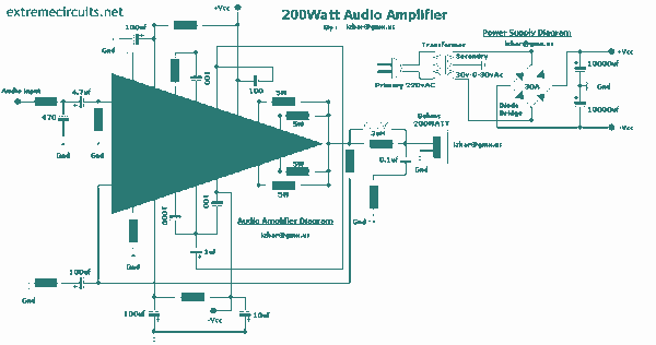
200 watt Audio amplifier with STK4050
This complete high quality, low noise mono audio power amplifier is based around the Hybrid Integrated Circuit STK4050 manufactured by Sanyo. The circuit incorporates volume and has a maximum music output power of 200W. The circuit incorporates an on board...