


2004 Chevy Tahoe: lost power 60 mph tachometer figuring
#Chevy Tahoe
#power loss
#tachometer
#fuse
#engine
#electrical issue
#automotive repair
#MAX fuse
#fuseblock
#connector
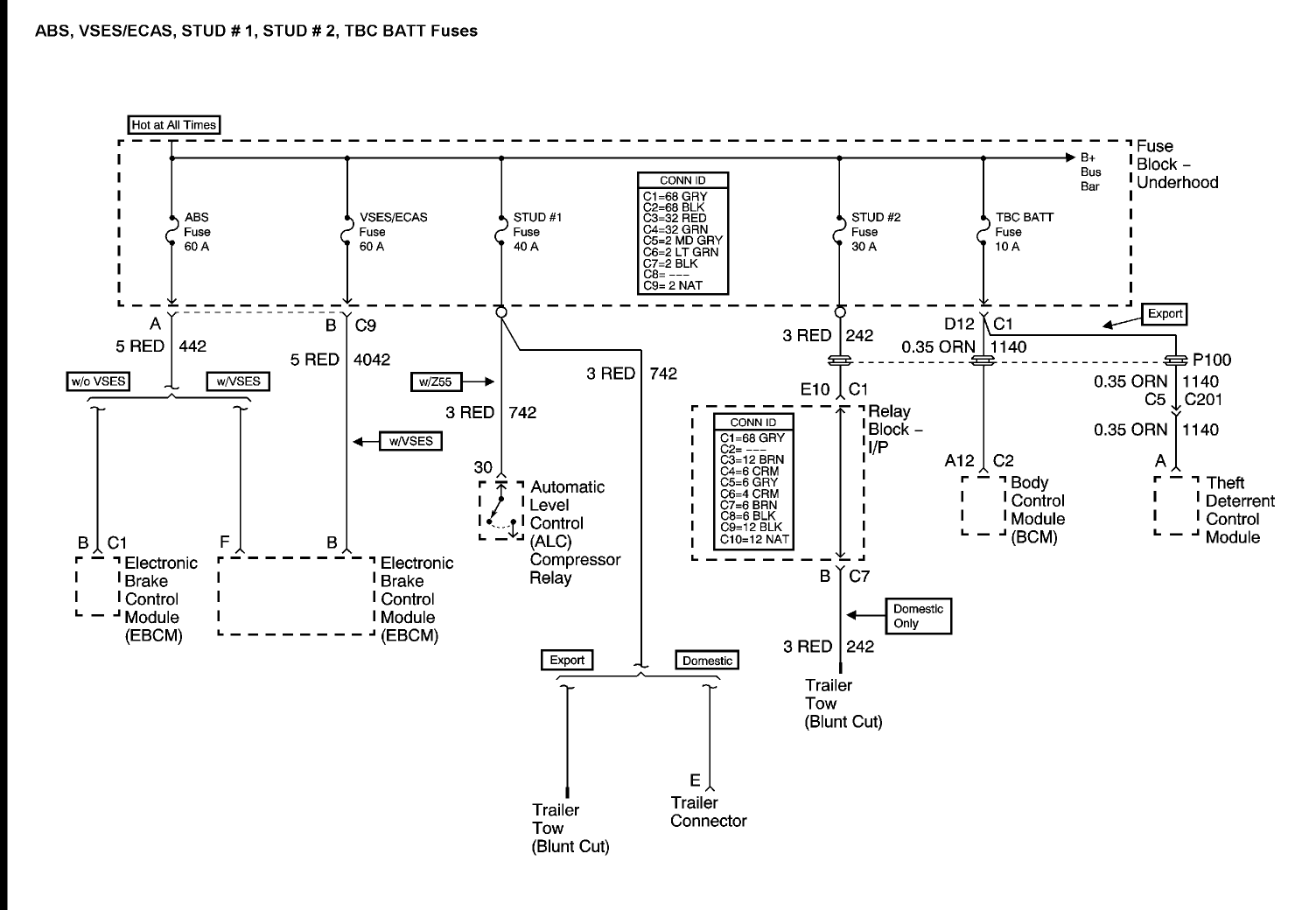
Description: A 2004 Chevy Tahoe lost power while driving at 60 mph, causing the tachometer to drop to zero. The vehicle has been in the shop for three days, and the mechanics are struggling to identify the issue. They have attempted several solutions, but the engine compartment fuse keeps blowing. The 30 amp MAX fuse in the underhood fuse block appears to connect directly to connector C1 at the interior Instrument Panel Relay Block and then to the Trailer Wiring. It is essential to confirm that the correct circuit causing the MAXI 30 amp fuse to blow is being examined, specifically labeled STUD #2, Circuit 242 with a red wire. The trailer's 6-way brown wire may be the source of the short circuit. The problem could be located either upstream or downstream of this area, necessitating isolation at the IP Relay Block connectors. Verification of the circuit is crucial, as this is the only 30 amp MAX fuse in the underhood fuse block. Identifying this short circuit on STUD #2 may also help resolve other related issues. If there is any uncertainty regarding the correct MAX fuse circuit, clarification is needed. The information is sourced from All Data, and inaccuracies regarding STUD #1 or STUD #2 could lead to misdirection. For quick inquiries, online platforms like JustAnswer may provide immediate assistance, especially as traffic to such sites has increased significantly.
The electrical system of a 2004 Chevy Tahoe includes a complex network of circuits that manage various functions, including engine management and auxiliary systems. The issue described involves a 30 amp MAX fuse that is integral to the operation of the vehicle's electrical components. The fuse is located in the underhood fuse block and is connected to critical components that include the Instrument Panel Relay Block and trailer wiring.
The primary concern is the consistent blowing of the 30 amp MAX fuse, which indicates a short circuit condition. The circuit in question, labeled STUD #2, is associated with Circuit 242, identifiable by a red wire. This circuit's integrity is crucial for the proper functioning of the vehicle's electrical systems. The potential short may lie within the wiring harness connecting the fuse to the IP Relay Block or the trailer wiring, particularly focusing on the 6-way brown wire, which is known to be a common point of failure.
To systematically diagnose the problem, it is recommended to isolate the circuit at the IP Relay Block connectors. This can be accomplished by disconnecting the connectors and testing for continuity and resistance in the wiring, ensuring that no unintended paths to ground are present. A multimeter can be utilized to check for shorts between the red wire and ground, as well as between the brown wire and ground, to identify any faults.
Furthermore, the investigation should include examining the integrity of the connectors and wiring for signs of wear, corrosion, or physical damage. If the circuit is verified to be intact, attention should shift to other components powered by the same fuse, such as relays or modules, which may also contribute to the short circuit condition.
Given the complexity of automotive electrical systems, it is advisable to consult detailed wiring diagrams and service manuals specific to the 2004 Chevy Tahoe for accurate troubleshooting procedures. This methodical approach will aid in pinpointing the source of the short circuit and restoring functionality to the vehicle's electrical system.A 2004 Chevy Tahoe that totally lost power. I was driving at 60 mph and watched my tachometer drop to nothing. It has been in the shop for three days now, and they are having trouble figuring out what is wrong. They have tried a couple things but the engine cpm fuse keeps blowing out. Any thoughts that may help The 30 amp MAX fuse in underhood fuseblock from here appears to be going directly to connector C1 at the interior Instrument Panel Relay Block and then to the Trailer Wiring. To be sure we are on the same page, can we verify that I am looking at the exact circuit that is shorting the MAXI 30 amp fuse. It should be labeled STUD #2. Circuit 242 3RED wire. Trailer 6-way brown may be area of short. Could be upstream or downstream of this area, but need to get to here and isolate at IP RElay Block connectors to be sure.
I hope we are on the correct circuit. The information I have here tell me this is the only MAX fuse 30 Amp in the underhood fuse block. And the information I have here tells me that this is the circuit to focus on. I am going to spend some time on the "U" codes for you next, but it is possible that finding this short on the STUD #2 30 A fuse may lead us to the other problems. If for any reason we are not on the correct MAX fuse circuit, let me know. I gather my information from All Data, and small error by them on say STUD #1 or STUD #2 can lead us way off in the wrong direction.
Ask-a-doc Web sites: If you`ve got a quick question, you can try to get an answer from sites that say they have various specialists on hand to give quick answers. Justanswer. com. Traffic on JustAnswer rose 14 percent. and had nearly 400, 000 page views in 30 days. inquiries related to stress, high blood pressure, drinking and heart pain jumped 33 percent.
The electrical system of a 2004 Chevy Tahoe includes a complex network of circuits that manage various functions, including engine management and auxiliary systems. The issue described involves a 30 amp MAX fuse that is integral to the operation of the vehicle's electrical components. The fuse is located in the underhood fuse block and is connected to critical components that include the Instrument Panel Relay Block and trailer wiring.
The primary concern is the consistent blowing of the 30 amp MAX fuse, which indicates a short circuit condition. The circuit in question, labeled STUD #2, is associated with Circuit 242, identifiable by a red wire. This circuit's integrity is crucial for the proper functioning of the vehicle's electrical systems. The potential short may lie within the wiring harness connecting the fuse to the IP Relay Block or the trailer wiring, particularly focusing on the 6-way brown wire, which is known to be a common point of failure.
To systematically diagnose the problem, it is recommended to isolate the circuit at the IP Relay Block connectors. This can be accomplished by disconnecting the connectors and testing for continuity and resistance in the wiring, ensuring that no unintended paths to ground are present. A multimeter can be utilized to check for shorts between the red wire and ground, as well as between the brown wire and ground, to identify any faults.
Furthermore, the investigation should include examining the integrity of the connectors and wiring for signs of wear, corrosion, or physical damage. If the circuit is verified to be intact, attention should shift to other components powered by the same fuse, such as relays or modules, which may also contribute to the short circuit condition.
Given the complexity of automotive electrical systems, it is advisable to consult detailed wiring diagrams and service manuals specific to the 2004 Chevy Tahoe for accurate troubleshooting procedures. This methodical approach will aid in pinpointing the source of the short circuit and restoring functionality to the vehicle's electrical system.A 2004 Chevy Tahoe that totally lost power. I was driving at 60 mph and watched my tachometer drop to nothing. It has been in the shop for three days now, and they are having trouble figuring out what is wrong. They have tried a couple things but the engine cpm fuse keeps blowing out. Any thoughts that may help The 30 amp MAX fuse in underhood fuseblock from here appears to be going directly to connector C1 at the interior Instrument Panel Relay Block and then to the Trailer Wiring. To be sure we are on the same page, can we verify that I am looking at the exact circuit that is shorting the MAXI 30 amp fuse. It should be labeled STUD #2. Circuit 242 3RED wire. Trailer 6-way brown may be area of short. Could be upstream or downstream of this area, but need to get to here and isolate at IP RElay Block connectors to be sure.
I hope we are on the correct circuit. The information I have here tell me this is the only MAX fuse 30 Amp in the underhood fuse block. And the information I have here tells me that this is the circuit to focus on. I am going to spend some time on the "U" codes for you next, but it is possible that finding this short on the STUD #2 30 A fuse may lead us to the other problems. If for any reason we are not on the correct MAX fuse circuit, let me know. I gather my information from All Data, and small error by them on say STUD #1 or STUD #2 can lead us way off in the wrong direction.
Ask-a-doc Web sites: If you`ve got a quick question, you can try to get an answer from sites that say they have various specialists on hand to give quick answers. Justanswer. com. Traffic on JustAnswer rose 14 percent. and had nearly 400, 000 page views in 30 days. inquiries related to stress, high blood pressure, drinking and heart pain jumped 33 percent.
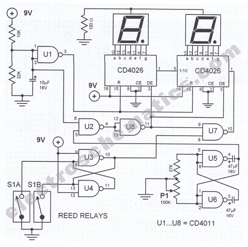
Digital Bike Tachometer Circuit
This digital DIY tachometer for bicycles utilizes two reed switches to gather speed information. The reed switches are positioned near the wheel rim, where permanent magnets are mounted on the wheel spokes. As the spokes rotate, the magnets pass by...
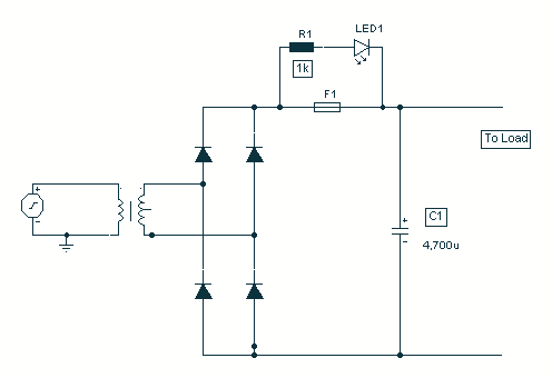
Fuse Monitor / Alarm
It came to me in a flash. A simple way to see if a fuse has blown without removing it from its holder. Its not often you can design a circuit using just two components, but with just one resistor...
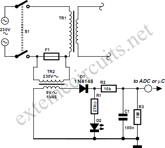
Isolated Fuse Fail Indicator
This circuit utilizes standard components to indicate the fuse status of mains-powered equipment while ensuring electrical isolation from the mains supply. A standard miniature low-power mains transformer (for example, with an output of approximately 6 V at 1.5 VA) serves...
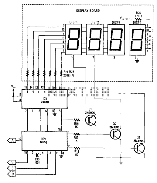
Digital Tachometer Counter
This circuit produces a readout for the digital tachometer circuit. IC9 is a 3-digit LED display driver, counter, and latch. IC8 drives the common-cathode LEDs, which are enabled by Q1, Q2, and Q3. See page 268, Fig. 46-5 for the...
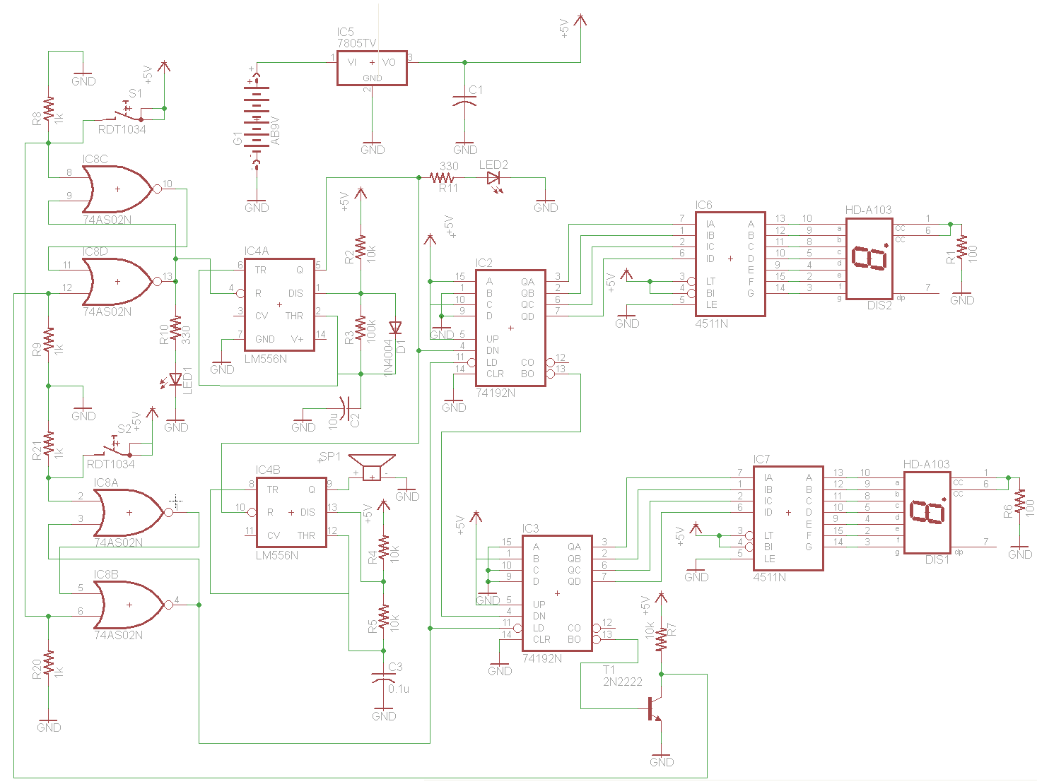
Build A Digital Tachometer/RPM Counter Circuit
The circuit for the Digital Tachometer/RPM Counter consists of a few components. They should be connected according to the provided circuit diagram. The PIC used is on a demonstration board, meaning the clock, power, and ground pins are already connected,...
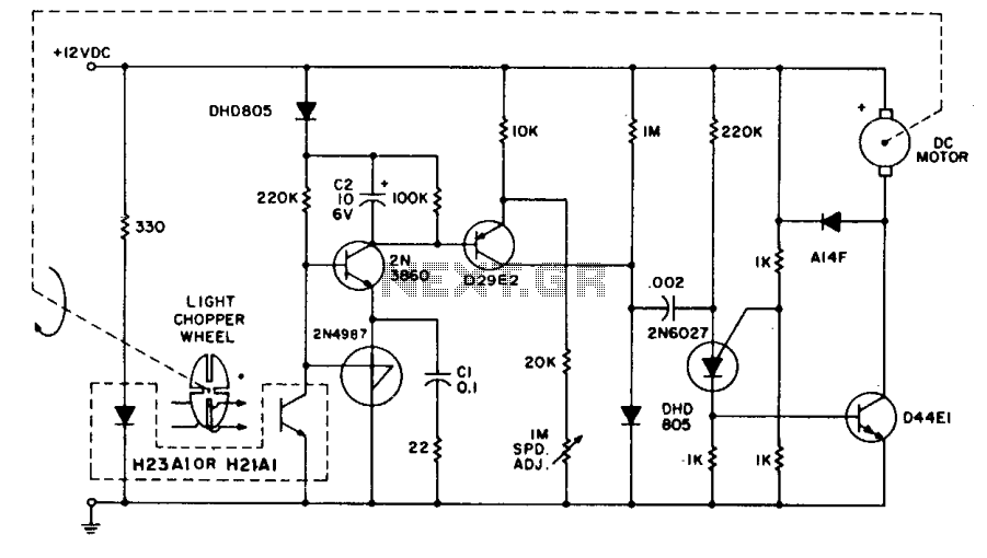
Tachometer feedback control
The system employs the H21A1 optocoupler and a chopper disc to achieve enhanced speed regulation. This is effective when the dynamic characteristics of both the motor system and the feedback system are appropriately matched, ensuring stability. The tachometer feedback system...
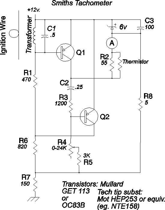
Smiths Tachometer
The process of calibrating the Smiths electronic tachometer revealed significant inaccuracies in its readings. A calibration technique was employed, similar to the one outlined in Tom Ballou's 1975 Tech Tip, using a dwell/tach meter at approximately 1200 RPM. This raised...
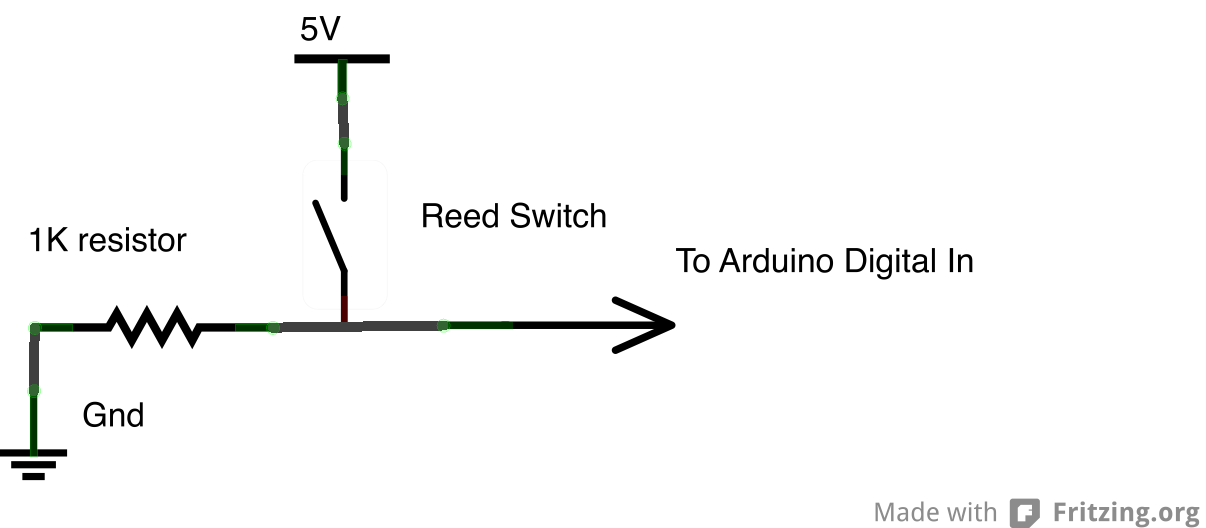
rear wheel tachometer
One of the goals of Movable Party is to provide an interactive experience for audiences and participants. Power will be generated from a hub motor attached to the rear wheel of each bike, with the speed of the rear wheel...
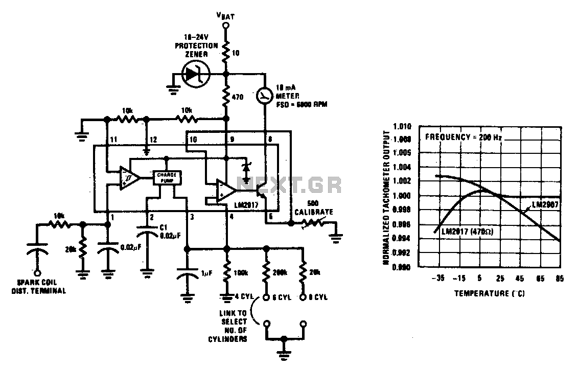
Gasoline engine tachometer
This tachometer can be configured for any number of cylinders by connecting the appropriate timing resistor as illustrated. A 500-ohm trim resistor can be utilized for final calibration. Additionally, a protection circuit consisting of a 10-ohm resistor and a Zener...