


2005 Yamaha DT125X Wiring Diagram Electrical Schematic
#Yamaha DT125X
#wiring diagram
#electrical schematic
#CDI unit
#rectifier/regulator
#ignition coil
#battery
#neutral switch
#main switch
#fuse
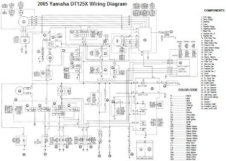
Description: The electrical system of the 2005 Yamaha DT125X typically includes a CDI unit, battery, thermo unit, rectifier/regulator, servomotor, fuse, neutral switch, ignition coil, and main switch.
The electrical schematic for the 2005 Yamaha DT125X outlines the interconnections and functionalities of the various components that comprise its electrical system. The CDI (Capacitor Discharge Ignition) unit plays a crucial role in the ignition system by controlling the timing and intensity of the spark delivered to the ignition coil. This component is essential for the efficient operation of the engine, as it ensures optimal combustion.
The battery serves as the primary power source for the electrical system, providing the necessary voltage for starting the engine and powering auxiliary systems such as lights and indicators. The thermo unit monitors the engine temperature, providing critical data to prevent overheating and ensuring the engine operates within safe temperature limits.
The rectifier/regulator is responsible for converting the AC voltage generated by the alternator into DC voltage suitable for charging the battery and powering the electrical components. This unit ensures that the voltage levels remain stable, preventing damage to sensitive electronic components.
The servomotor is typically involved in controlling various mechanical functions, such as throttle position or other actuators, allowing for responsive adjustments based on input from the rider or the vehicle's control systems. The fuse provides overcurrent protection, safeguarding the electrical system from potential damage due to short circuits or overloads.
The neutral switch is a safety feature that indicates whether the transmission is in neutral, preventing accidental starts when the bike is in gear. The main switch controls the overall power to the electrical system, allowing the rider to turn the system on or off as needed.
Overall, the electrical system of the 2005 Yamaha DT125X is designed to provide reliable performance, ensuring that all components work together seamlessly for optimal operation of the motorcycle. Proper understanding of the schematic is essential for troubleshooting and maintenance of the system.Usually, the electrical system of the 2005 Yamaha DT125X consists of CDI unit, battery, thermo unit, rectifier/regulator servomotor, fuse, neutral switch, ignition coil and main switch. (click image to enlarge)
The electrical schematic for the 2005 Yamaha DT125X outlines the interconnections and functionalities of the various components that comprise its electrical system. The CDI (Capacitor Discharge Ignition) unit plays a crucial role in the ignition system by controlling the timing and intensity of the spark delivered to the ignition coil. This component is essential for the efficient operation of the engine, as it ensures optimal combustion.
The battery serves as the primary power source for the electrical system, providing the necessary voltage for starting the engine and powering auxiliary systems such as lights and indicators. The thermo unit monitors the engine temperature, providing critical data to prevent overheating and ensuring the engine operates within safe temperature limits.
The rectifier/regulator is responsible for converting the AC voltage generated by the alternator into DC voltage suitable for charging the battery and powering the electrical components. This unit ensures that the voltage levels remain stable, preventing damage to sensitive electronic components.
The servomotor is typically involved in controlling various mechanical functions, such as throttle position or other actuators, allowing for responsive adjustments based on input from the rider or the vehicle's control systems. The fuse provides overcurrent protection, safeguarding the electrical system from potential damage due to short circuits or overloads.
The neutral switch is a safety feature that indicates whether the transmission is in neutral, preventing accidental starts when the bike is in gear. The main switch controls the overall power to the electrical system, allowing the rider to turn the system on or off as needed.
Overall, the electrical system of the 2005 Yamaha DT125X is designed to provide reliable performance, ensuring that all components work together seamlessly for optimal operation of the motorcycle. Proper understanding of the schematic is essential for troubleshooting and maintenance of the system.Usually, the electrical system of the 2005 Yamaha DT125X consists of CDI unit, battery, thermo unit, rectifier/regulator servomotor, fuse, neutral switch, ignition coil and main switch. (click image to enlarge)
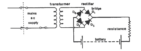
Battery Charging On Board Ship
Batteries serve as one of the energy sources available on vessels, utilized during blackouts and emergency situations aboard a ship. These batteries are employed for low-voltage DC systems, such as bridge navigational instruments, and must be kept charged to provide...
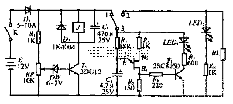
Tip a battery discharge control circuit
The discharge control circuit consists of a battery management system designed to prevent over-discharge of a battery. It features a relay control mechanism that activates when the battery voltage drops below a specified threshold of approximately 10.5V. The circuit includes...
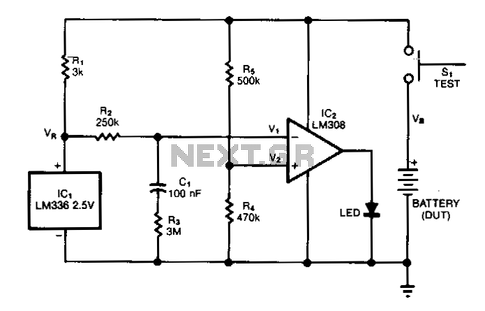
Battery-capacity-tester
The test circuit indicates the remaining capacity of a battery by measuring the duration, in seconds, that an LED remains illuminated after the test switch (S1) is activated. This circuit has demonstrated reliability in testing nickel-cadmium (NiCad), carbon, and alkaline...
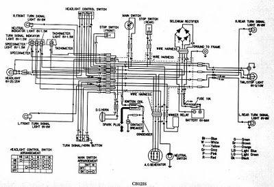
CB125S WIRING DIAGRAM
CB125S Wiring Diagram Manual PDF Download.
The CB125S Wiring Diagram Manual provides a comprehensive guide for understanding the electrical system of the CB125S motorcycle. This manual includes detailed wiring diagrams that illustrate the connections between various electrical components, such as the...
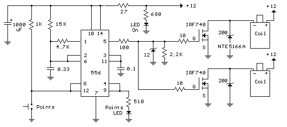
Automotive ignition coil
Here's a circuit to create a buzzcoil using a standard automotive ignition coil. A 556 dual timer is used to establish the frequency and duty cycle of the coil current. One of the timers is used as an oscillator to...
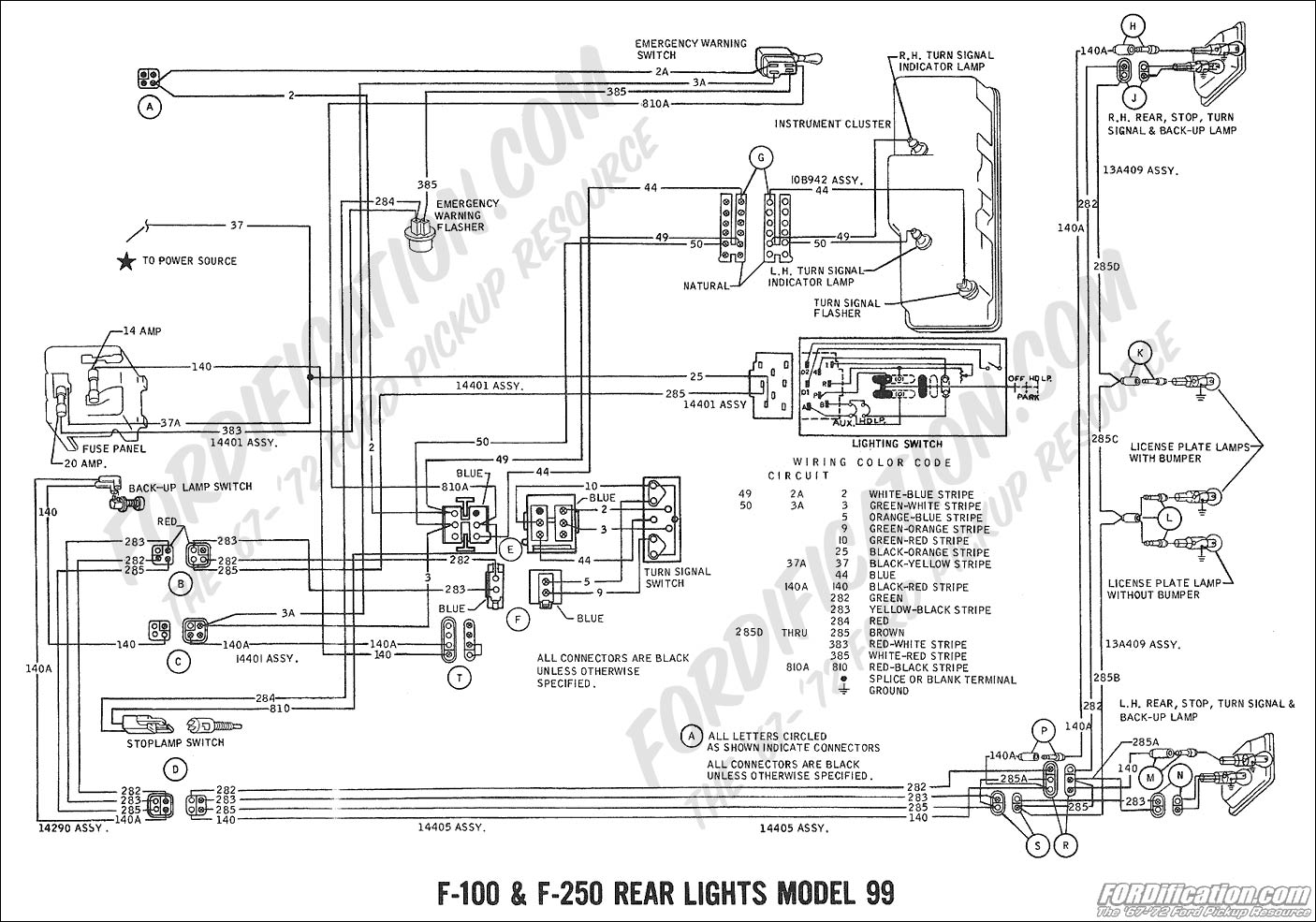
99 CIVIC WIRING DIAGRAM COURTESY LIGHTS
1999 Civic Wiring Diagram for Courtesy Lights Manual PDF.
The 1999 Civic Wiring Diagram for courtesy lights provides a comprehensive visual representation of the electrical connections and components associated with the vehicle's interior lighting system. This schematic is essential for understanding...
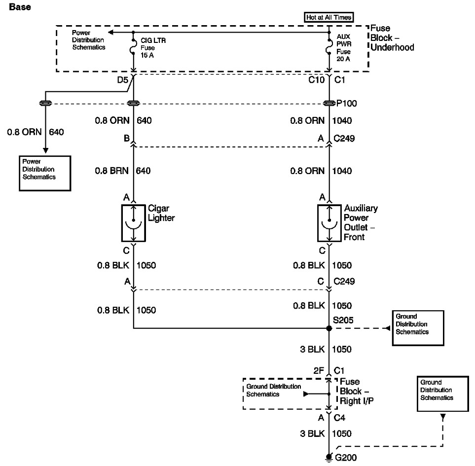
auxillary fuse lighter fuse burned out
The provided information includes a fuse block diagram with the Auxiliary Power (Aux Pwr) fuse highlighted. It is advisable to check both sides of the fuse using a test light or multimeter to ensure functionality. It is assumed that power...
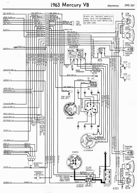
mercury v8 monterey 1963 wiring diagram
This document presents the wiring diagram for the 1963 Mercury V8 Monterey, specifically focusing on the right side of the diagram. The left side of the wiring diagram has been previously detailed. The right side diagram provides a clear representation...
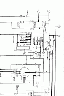
1986 honda civic wiring diagram
The wiring diagram for the 1986 Honda Civic includes components such as the neutral switch, automatic choke heater, charge warning light, resistor, starter motor, starter solenoid, thermo switch, regulator, alternator, distributor, igniter, ignition coil, spark plugs, and air temperature sensor.
The...