


240Z Headlight Relay Mod
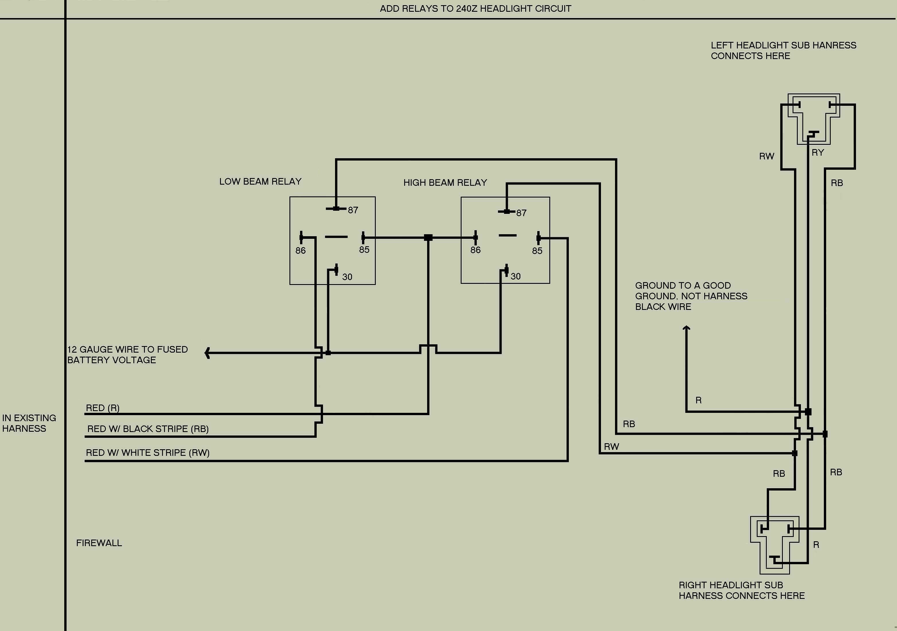
Description: The following is a modification of the headlight wiring for 240Z vehicles. This modification is designed to reduce the current load on the headlight switch by redistributing it to two relays, thereby allowing more current to reach the lights simultaneously. This circuit is intended to be integrated into the stock 240Z wiring harness located on the right fender well. The wire colors used correspond to those of the 1973 240Z, although it is believed that they are consistent across all model years. The relevant wires can be found in the harness between the firewall and the connector situated in front of the radiator support, where the right headlight sub-harness connects. The connector is T-shaped and features three male blades. The wire on the left is red with a black stripe (RB). In the original equipment (OE) 240Z wiring, this wire is grounded when the low/high beam switch is in the low beam position. The wire on the right is red with a white stripe (RW) on the left headlight; however, on the right headlight, it is also red with a black stripe. From the high/low beam switch, it is red with a white stripe. In the OE 240Z wiring, this wire is grounded when the low/high beam switch is in the high beam position. The wire on the bottom is red without a stripe (R) for the right headlight and red with a yellow stripe (RY) for the left headlight. In the OE 240Z wiring, these wires connect to the left and right headlight fuses.
This headlight wiring modification enhances the performance of the 240Z's lighting system by utilizing relays, which serve as electrically operated switches. By doing so, the modification alleviates the strain on the original headlight switch, which can be prone to wear and failure due to excessive current draw. The relays are typically rated for higher current capacities, allowing them to handle the load more efficiently.
The installation process begins with locating the specified wires in the wiring harness. The T-shaped connector is a critical junction point, and careful identification of the wire colors is essential to ensure proper connections. The wires should be spliced correctly to the relay circuit to maintain functionality. The RB wire should connect to the relay that activates the low beams, while the RW wire should connect to the relay for the high beams. The R and RY wires will be connected to the respective headlight fuses, ensuring that power is supplied to the headlights through the relays.
When implementing this modification, attention must be paid to the relay specifications, including coil voltage and contact ratings, to match the vehicle's electrical system. Additionally, proper insulation and securing of connections are necessary to prevent short circuits or disconnections due to vibrations or environmental factors. This modification not only improves the brightness of the headlights but also enhances the overall reliability of the vehicle's electrical system.The following is my modification of the Headlight wiring for 240Z`s. I made this modification in order to take the current load off of the Headlight switch and put the load onto two relays, giving more current to the lights at the same time. This circuit is intended to be installed by splicing it into the stock 240Z wiring harness on the right fen
derwell. I used wire colors for the 73 240Z, although I believe they are the same for all years. Find the following wires in the harness between the firewall and the connector in front of the radiator support that the right headlight sub-harness plugs into. The connector is T shaped with three male blades in it: The wire on the left is Red with a Black stripe (RB).
In the OE 240Z wiring, this wire is grounded when the low/high beam switch is in the low beam "position". The wire on the right is Red with a White stripe (RW) (on the left headlight). Unfortunately, on the right headlight it is also Red with a Black stripe. From the high/low beam switch it is Red with a White Stripe. In the OE 240Z wiring, this wire is grounded when the low/high beam switch is in the high beam "position".
The wire on the bottom is Red with no stripe (R) on the Right headlight, and Red with Yellow stripe (RY) on the Left headlight. In the OE 240Z wiring, these wires go to the left and right headlight fuses.
This headlight wiring modification enhances the performance of the 240Z's lighting system by utilizing relays, which serve as electrically operated switches. By doing so, the modification alleviates the strain on the original headlight switch, which can be prone to wear and failure due to excessive current draw. The relays are typically rated for higher current capacities, allowing them to handle the load more efficiently.
The installation process begins with locating the specified wires in the wiring harness. The T-shaped connector is a critical junction point, and careful identification of the wire colors is essential to ensure proper connections. The wires should be spliced correctly to the relay circuit to maintain functionality. The RB wire should connect to the relay that activates the low beams, while the RW wire should connect to the relay for the high beams. The R and RY wires will be connected to the respective headlight fuses, ensuring that power is supplied to the headlights through the relays.
When implementing this modification, attention must be paid to the relay specifications, including coil voltage and contact ratings, to match the vehicle's electrical system. Additionally, proper insulation and securing of connections are necessary to prevent short circuits or disconnections due to vibrations or environmental factors. This modification not only improves the brightness of the headlights but also enhances the overall reliability of the vehicle's electrical system.The following is my modification of the Headlight wiring for 240Z`s. I made this modification in order to take the current load off of the Headlight switch and put the load onto two relays, giving more current to the lights at the same time. This circuit is intended to be installed by splicing it into the stock 240Z wiring harness on the right fen
derwell. I used wire colors for the 73 240Z, although I believe they are the same for all years. Find the following wires in the harness between the firewall and the connector in front of the radiator support that the right headlight sub-harness plugs into. The connector is T shaped with three male blades in it: The wire on the left is Red with a Black stripe (RB).
In the OE 240Z wiring, this wire is grounded when the low/high beam switch is in the low beam "position". The wire on the right is Red with a White stripe (RW) (on the left headlight). Unfortunately, on the right headlight it is also Red with a Black stripe. From the high/low beam switch it is Red with a White Stripe. In the OE 240Z wiring, this wire is grounded when the low/high beam switch is in the high beam "position".
The wire on the bottom is Red with no stripe (R) on the Right headlight, and Red with Yellow stripe (RY) on the Left headlight. In the OE 240Z wiring, these wires go to the left and right headlight fuses.
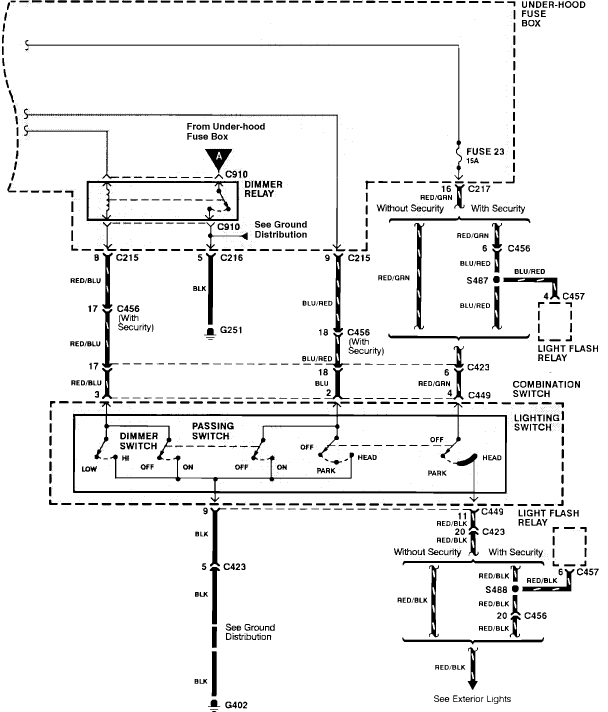
Head light high beam the dimmer relay or the fuses for that circuit
Grounding the blue wire at the headlamp switch causes the lights to illuminate, indicating a faulty switch. Continuity of the switch has already been verified. The relay consists of two small terminals and two larger ones. The smaller terminal, which...
Simple Headlight Reminders
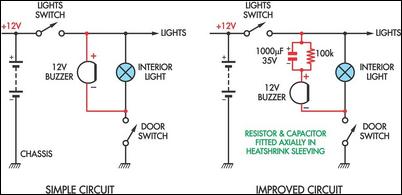
Two headlight reminder circuits are simple to install and operate based on the KISS (Keep It Simple Stupid) principle. The basic circuit consists of a 12V piezo buzzer connected between the lights circuit and a door switch. The buzzer activates...
HIGHWAY ALERT SIGNAL LAMP
The lighting system of a motor vehicle comprises lighting and signaling devices mounted or integrated at the front, sides, rear, and sometimes the top of the vehicle. This system's purpose is to provide illumination for the driver to operate the...
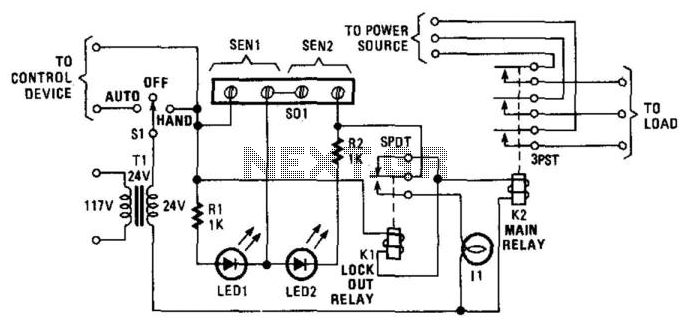
Universal Power Controller
Relay K1 features a low-impedance coil, while Relay K2 is equipped with a high-impedance coil. When a sensor opens, current flows through the coil of K1, activating it. This action opens the contacts of K1, thereby preventing the reclosure of...
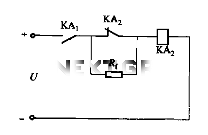
DC relay circuit to accelerate the release
A DC relay or contactor is utilized to enhance the excitation pull-in and release mechanisms in a circuit. The relay circuit, as depicted in Figure 6-28, facilitates improved return line efficiency. When the control relay KAi is activated, its normally...
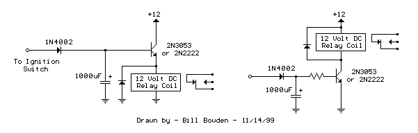
Power Off Delay Relay circuits
The two circuits below illustrate opening a relay contact a short time after the ignition or light switch is turned off. The capacitor is charged and the relay is closed when the voltage at the diode anode rises to +12...
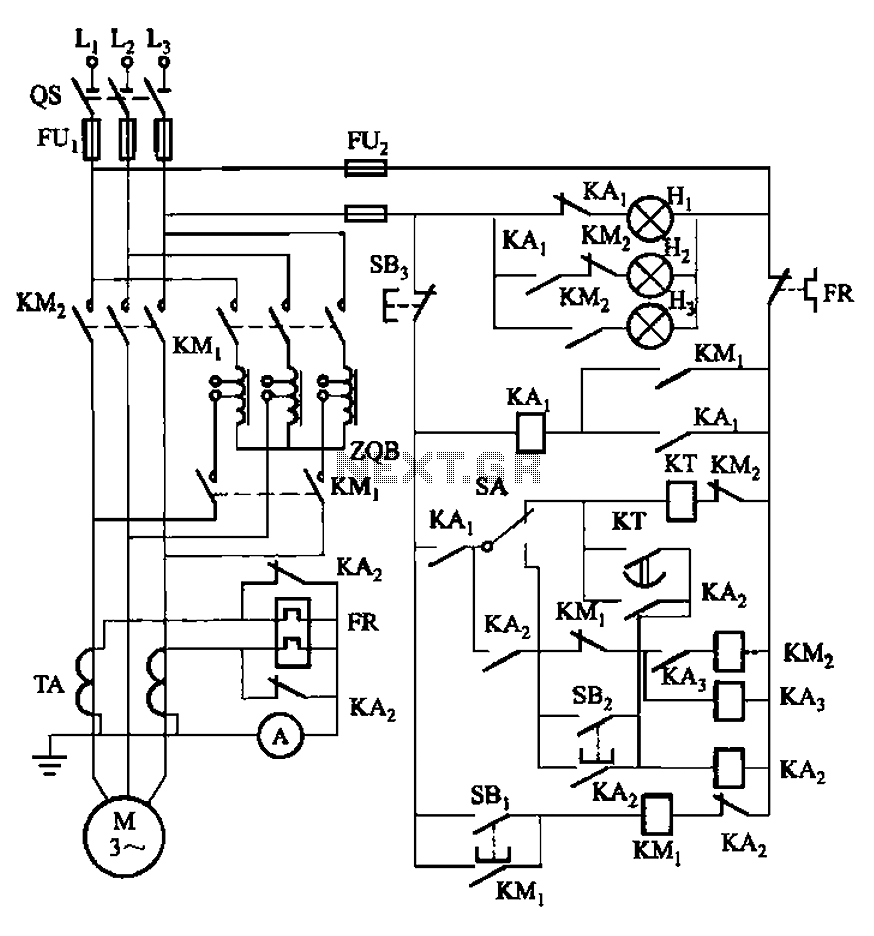
Can effectively guarantee the auto-voltage starting circuit main contact of extinction
The circuit illustrated in Figure 3-56 features both manual and automatic start-up modes. It incorporates two relays, KA2 and KA3, within the control loop. The circuit design ensures that KM1 is cut off before and after activating KM2. A main...
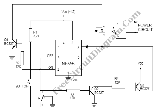
Alternating Relay Switch
A reader named Andrea ([email protected]) submitted a circuit designed for educational purposes. The primary objective is to demonstrate how to electronically toggle an output state using only a push-button switch. According to Andrea, this simple circuit can drive a monostable...
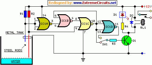
Water Pump Relay Controller Circuit
This circuit utilizes a relay to control a water pump, enabling automatic level management of a water reservoir or well. The shorter steel rod functions as the "water high" sensor, while the longer rod serves as the "water low" sensor....