


74C164 8 bit shift register work as a heart for car LED light sequencer
#74C164
#shift register
#LED sequencer
#CMOS
#car lights
#8-bit
#serial shift
#parallel-out
#D-type flip-flop
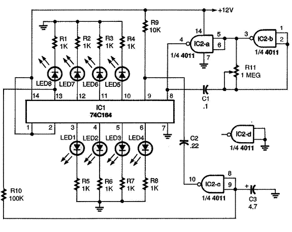
Description: The Car LED Light Sequencer utilizes a standard 74C164 8-bit shift register as its main component. The 74C164, also referred to as an 8-Bit Parallel-Out Serial Shift Register, is a monolithic complementary MOS (CMOS) integrated circuit. This 8-bit shift register features gated serial inputs and a clear function. Each register bit functions as a D-type master/slave flip-flop. Data is serially shifted into and out of the 8-bit register during the positive transition of the clock pulse. The clear function operates independently of the clock and is activated by a low level at the clear input. The device supports a wide supply voltage range from 3V to 15V DC. Input data is fed into the serial inputs at pins 1 and 2, which are connected to the circuit's VCC. When pins 1 and 2 are high, data shifts one step forward with each clock pulse. The outputs are located at pins 3-6 and 10-13, with data flowing from output 1 to 2 to 3 and so on with each positive edge of the clock pulse. The data can be reset to zero by applying a momentary low input at pin 9. Two gates of the 4011 quad two-input NAND gate (IC2-a and IC2-b) are configured as an astable oscillator circuit, with the operating frequency determined by capacitor C1 and resistor R11. The positive output pulses from pin 4 of IC2 are connected to the clock input of the 74C164. An LED, along with a 1K resistor, is connected to each output of the shift register. The eighth output at pin 13 is linked through an RC network delay circuit comprising resistor R10 and capacitor C3. When the eighth clock pulse activates LED8, pin 13 of IC1 goes high, charging C3. After a certain duration, the output from IC2-c goes low, clearing the outputs of the shift register. The first clock pulse illuminates LED1, followed sequentially by LED2, LED3, and so forth until all eight LEDs are lit. After the eighth LED is activated, the clear pulse from IC2-c turns off all LEDs, and the sequence restarts. The values of R10 and C3 can be adjusted to ensure that LED8 remains illuminated for the same duration as the other LEDs. To achieve a faster sequence, the RC time delay circuit can be shortened by decreasing the values of R10 or C3, and vice versa for a slower sequence.
The Car LED Light Sequencer circuit is designed for automotive applications where visual signaling is essential. The 74C164 shift register serves as the core for controlling multiple LEDs in a sequential manner. The astable multivibrator configuration using the 4011 NAND gates generates a clock signal that drives the shifting process, ensuring that each LED lights up in succession, creating an appealing visual effect. The choice of a CMOS technology for the shift register allows for low power consumption and compatibility with a wide range of supply voltages, making it suitable for automotive environments.
The design includes provisions for adjusting the timing of the LED sequence through the RC delay circuit. By selecting appropriate values for R10 and C3, the duration for which the eighth LED remains lit can be fine-tuned, allowing for customization based on user preference or specific application requirements. This flexibility enhances the usability of the sequencer in various lighting applications, whether for decorative purposes or functional signaling.
Overall, the Car LED Light Sequencer is a robust and versatile circuit that can be integrated into various automotive lighting systems, providing both aesthetic and functional benefits. The use of standard components like the 74C164 and 4011 NAND gates ensures ease of sourcing and assembly, making it an accessible project for electronics enthusiasts and professionals alike.This Car LED Light Sequencer uses a standard 74C164 8 bit shift register as its heart of operation. The 74C164 is also known as a 8-Bit Parallel-Out Serial Shift Register which is a monolithic complementary MOS (CMOS) integrated circuit. These 8-bit shift registers have gated serial inputs and clear. Each register bit is a D-type master/slave flip -flop. Data is serially shifted in and out of the 8-bit register during the positive going transition of clock pulse. Clear is independent of the clock and accomplished by a low level at the clear input. It has a wide supply voltage range from 3V to 15V DC. The input data goes to the serial inputs at pin 1 and 2 which are connected to VCC of the circuit. When pins 1 and 2 are high, the data moves one step forward with each clock pulse. As shown in the diagram above, the outputs are pins 3-6 and 10-13. The data flows from output 1 to 2 to 3. to 8 with each positive edge of the clock pulse. The data can be cleared to zero by putting a momentary low input at pin 9. Two gates of 4011 quad two input NAND gate IC2-a and IC2-b are connected as an astable oscillator circuit with the frequency of operation set by C1 and R11.
The clock`s positive output pulses at pin 4 of IC2 are connected to the clock input of 74C164. An LED with a resistor of 1K each is connected to the outputs of the shift register. The shift register`s 8th output atpin 13 is connected through a RC network delay circuit of R10 and C3. When the 8th clock pulse turns on LED8, pin 13 of IC1 goes positive, charging C3. After a period of time, IC2-c output goes low clearing the shift register outputs. The first clock pulse turns LED1 on, the second LED2, the third LED3 until all eight of the LEDs are lighted ON.
After the8th LED turns ON, the clear pulse from IC2-c turns OFF all the LEDs and the sequence is repeated. The values of R10 and C3 may be varied to allow LED8 to remain ON for the same time period as each of the other LEDs.
The RC time delay circuit will need to be shorter for a faster sequence by decresing the R10 or C3 and vice versa.
The Car LED Light Sequencer circuit is designed for automotive applications where visual signaling is essential. The 74C164 shift register serves as the core for controlling multiple LEDs in a sequential manner. The astable multivibrator configuration using the 4011 NAND gates generates a clock signal that drives the shifting process, ensuring that each LED lights up in succession, creating an appealing visual effect. The choice of a CMOS technology for the shift register allows for low power consumption and compatibility with a wide range of supply voltages, making it suitable for automotive environments.
The design includes provisions for adjusting the timing of the LED sequence through the RC delay circuit. By selecting appropriate values for R10 and C3, the duration for which the eighth LED remains lit can be fine-tuned, allowing for customization based on user preference or specific application requirements. This flexibility enhances the usability of the sequencer in various lighting applications, whether for decorative purposes or functional signaling.
Overall, the Car LED Light Sequencer is a robust and versatile circuit that can be integrated into various automotive lighting systems, providing both aesthetic and functional benefits. The use of standard components like the 74C164 and 4011 NAND gates ensures ease of sourcing and assembly, making it an accessible project for electronics enthusiasts and professionals alike.This Car LED Light Sequencer uses a standard 74C164 8 bit shift register as its heart of operation. The 74C164 is also known as a 8-Bit Parallel-Out Serial Shift Register which is a monolithic complementary MOS (CMOS) integrated circuit. These 8-bit shift registers have gated serial inputs and clear. Each register bit is a D-type master/slave flip -flop. Data is serially shifted in and out of the 8-bit register during the positive going transition of clock pulse. Clear is independent of the clock and accomplished by a low level at the clear input. It has a wide supply voltage range from 3V to 15V DC. The input data goes to the serial inputs at pin 1 and 2 which are connected to VCC of the circuit. When pins 1 and 2 are high, the data moves one step forward with each clock pulse. As shown in the diagram above, the outputs are pins 3-6 and 10-13. The data flows from output 1 to 2 to 3. to 8 with each positive edge of the clock pulse. The data can be cleared to zero by putting a momentary low input at pin 9. Two gates of 4011 quad two input NAND gate IC2-a and IC2-b are connected as an astable oscillator circuit with the frequency of operation set by C1 and R11.
The clock`s positive output pulses at pin 4 of IC2 are connected to the clock input of 74C164. An LED with a resistor of 1K each is connected to the outputs of the shift register. The shift register`s 8th output atpin 13 is connected through a RC network delay circuit of R10 and C3. When the 8th clock pulse turns on LED8, pin 13 of IC1 goes positive, charging C3. After a period of time, IC2-c output goes low clearing the shift register outputs. The first clock pulse turns LED1 on, the second LED2, the third LED3 until all eight of the LEDs are lighted ON.
After the8th LED turns ON, the clear pulse from IC2-c turns OFF all the LEDs and the sequence is repeated. The values of R10 and C3 may be varied to allow LED8 to remain ON for the same time period as each of the other LEDs.
The RC time delay circuit will need to be shorter for a faster sequence by decresing the R10 or C3 and vice versa.
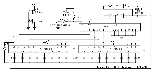
16 stage bi directional led sequencer
The bi-directional sequencer employs a 4-bit binary up/down counter (CD4516) along with two "1 of 8 line decoders" (74HC138 or 74HCT138) to create the well-known "Night Rider" display. A Schmitt Trigger oscillator generates the clock signal for the counter, and...
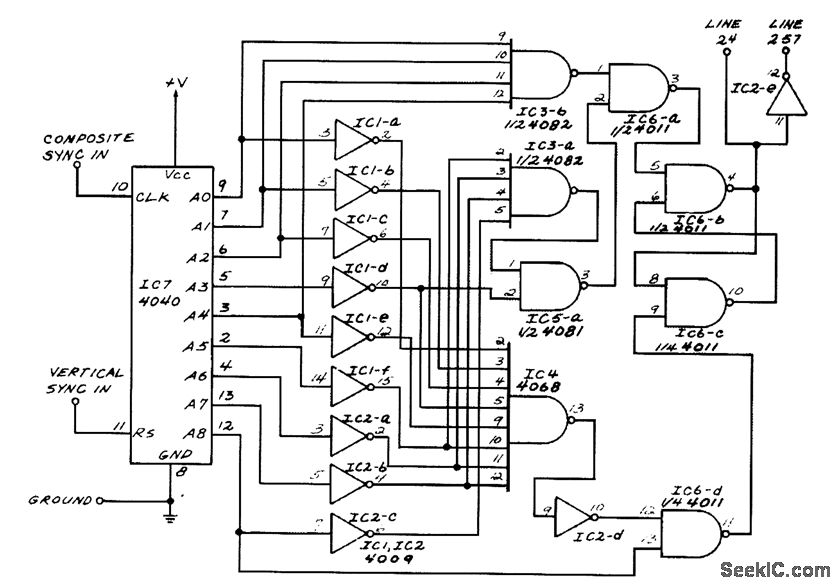
TV LINE DECODER I
This circuit generates outputs on TV lines 24 and 257. It was utilized for a decoder circuit and employs a CMOS counter along with gate logic. Only one pin is designated for the output line indicator.
The circuit described serves a...
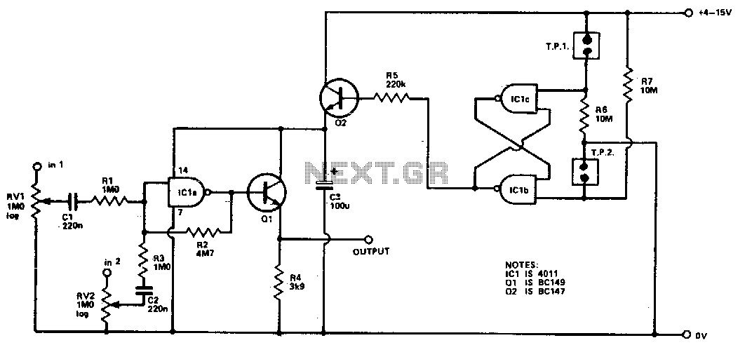
Cmos mixer
Four inputs can be mixed by duplicating the circuit to the left of C3 and using the fourth gate of ICI. Two gates are used in a touch-operated switching circuit that controls the voltage on the base of switching transistor...
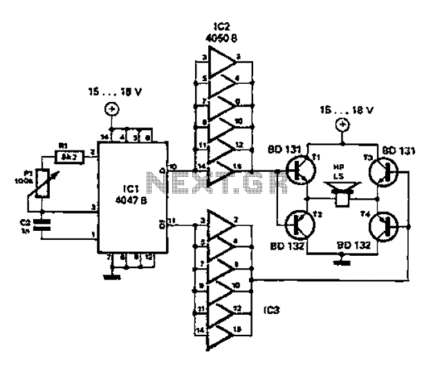
Simple circuit diagram repellent
A low-cost and straightforward repellent circuit can be utilized for deterring rats, mice, and other animals, as illustrated in the electronic figure below. The circuit employs a CMOS integrated circuit of type 4047, which functions as a relaxation oscillator. Its...
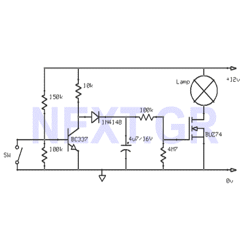
In-Car lights delay circuit
This circuit gradually switches the internal lights of a car on and off. The delay time can be adjusted by changing the values of the 10k and 4.7M resistors, as well as the capacitor.
The circuit operates by utilizing a timing...
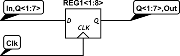
Shift register on a schematic
The circuit features a shift register chip (74HC595N), which is not available on CircuitLab. There may be a specific representation for a shift register in schematic diagrams. Although assistance with CircuitLab is not provided, schematic illustrations can be referenced on...
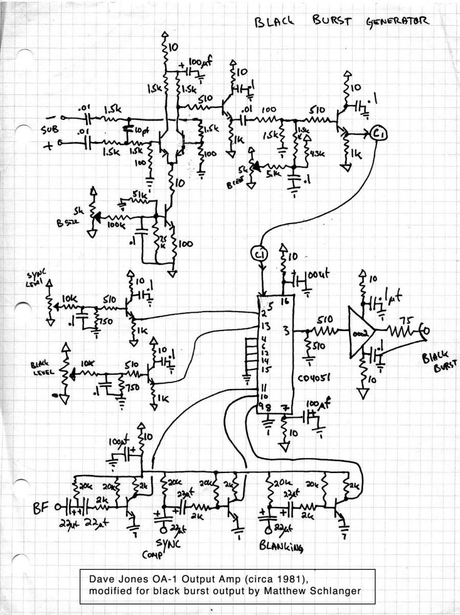
Black Burst Generator
CMOS analog multiplexers are commonly utilized in electronic circuits for various applications. This document presents a modified circuit based on a design by Dave Jones, aimed at constructing a black burst generator. Sync signals are essential in video systems to...
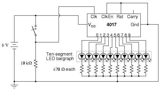
LED sequencer
The model 4017 integrated circuit is a CMOS counter with ten output terminals. One of these ten terminals will be in a "high" state at any given time, with all others being "low," giving a "one-of-ten" output sequence. If low-to-high...
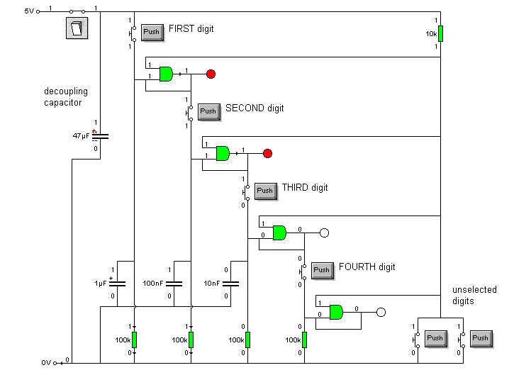
4081 AND gates
The inputs of the gate must be connected to either LOW or HIGH and must not be left open circuit. This is achieved through the use of input switches along with their pull-down resistors. To prevent loading on the gate's...