


Add a Discrete Jack-Sensing Circuit to the MAX13330/MAX13331 Automotive Headphone Amplifier
#headphone amplifier
#jack-sensing
#audio jack
#MAX13330
#MAX13331
#DirectDrive
#automotive audio
#circuit addition
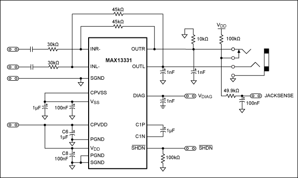
Description: Incorporate a straightforward, economical jack-sensing circuit (JACKSENSE) into a DirectDrive automotive headphone amplifier to detect when headphones are plugged into the audio jack.
The implementation of a jack-sensing circuit (JACKSENSE) in a DirectDrive automotive headphone amplifier is designed to enhance user experience by providing a reliable detection mechanism for headphone insertion. The circuit typically utilizes a combination of resistors, transistors, and possibly a microcontroller to monitor the state of the audio jack.
The circuit functions as follows: when a headphone plug is inserted into the audio jack, it completes a circuit that changes the voltage levels at a designated sensing point. This change can be detected using a voltage divider network or a comparator circuit. The output signal can then be used to enable or disable the audio output to the headphones, ensuring that sound is only directed to the headphones when they are connected.
In a basic design, a pull-down resistor may be connected to the ground, while a signal line is connected to the tip of the headphone jack. When the headphone is inserted, the resistance changes, which can be interpreted by a microcontroller or a simple transistor switch. This allows the amplifier to switch states and prevent audio signals from being sent to the speakers, thereby protecting the equipment and enhancing sound quality.
To ensure reliability, the circuit may also include debounce logic to prevent false triggering from the mechanical contact of the headphone jack. The overall design should prioritize low power consumption, compact size, and cost-effectiveness, making it suitable for automotive applications where space and energy efficiency are critical.
In conclusion, the integration of a jack-sensing circuit into a DirectDrive headphone amplifier not only improves functionality but also contributes to a more seamless user interface in automotive audio systems.Add a simple, low-cost, jack-sensing circuit (JACKSENSE) to a DirectDrive automotive headphone amp and detect when a headphone is inserted into the audio jack..
The implementation of a jack-sensing circuit (JACKSENSE) in a DirectDrive automotive headphone amplifier is designed to enhance user experience by providing a reliable detection mechanism for headphone insertion. The circuit typically utilizes a combination of resistors, transistors, and possibly a microcontroller to monitor the state of the audio jack.
The circuit functions as follows: when a headphone plug is inserted into the audio jack, it completes a circuit that changes the voltage levels at a designated sensing point. This change can be detected using a voltage divider network or a comparator circuit. The output signal can then be used to enable or disable the audio output to the headphones, ensuring that sound is only directed to the headphones when they are connected.
In a basic design, a pull-down resistor may be connected to the ground, while a signal line is connected to the tip of the headphone jack. When the headphone is inserted, the resistance changes, which can be interpreted by a microcontroller or a simple transistor switch. This allows the amplifier to switch states and prevent audio signals from being sent to the speakers, thereby protecting the equipment and enhancing sound quality.
To ensure reliability, the circuit may also include debounce logic to prevent false triggering from the mechanical contact of the headphone jack. The overall design should prioritize low power consumption, compact size, and cost-effectiveness, making it suitable for automotive applications where space and energy efficiency are critical.
In conclusion, the integration of a jack-sensing circuit into a DirectDrive headphone amplifier not only improves functionality but also contributes to a more seamless user interface in automotive audio systems.Add a simple, low-cost, jack-sensing circuit (JACKSENSE) to a DirectDrive automotive headphone amp and detect when a headphone is inserted into the audio jack..
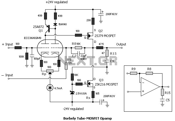
Headphone Amplifier circuits
This article discusses several opamp-based headphone amplifier circuits, including suggestions for selecting opamps, input coupling and filtering, high current output stages and power supply options. There are no recommendations for specific opamp brands or models. For tube devotees, there is...
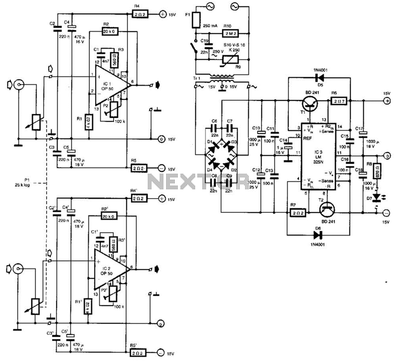
Headphone Amplifier Circuit
Built around Precision Monolithics Inc. OP-50 operational amplifiers, this amplifier is capable of driving 100- to 14-ohm headphones. It maintains a flat frequency response within 0.4 dB from 10 Hz to 20 kHz and exhibits a total harmonic distortion (THD)...
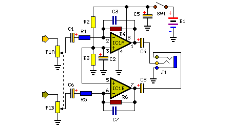
9 volt headphone amplifier
The decision to design a 9V powered headphone amplifier has been finalized. The primary requirement was to power the circuit using a common PP3 (transistor radio) alkaline battery. The introduction of the 5534 low-noise op-amp at a reasonable price has...
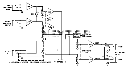
Distribution Amplifier
The Model HC 6 Headphone Console is a six channel headphone amplifier, consisting of six stereo amplifiers, two master stereo inputs and six individual stereo inputs. The two master stereo inputs feed a separate left and right bus to each...
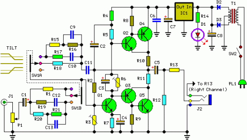
Pure Class-A Headphone Amplifier Schematic
The described shunt-feedback configuration facilitates the straightforward integration of frequency-dependent networks to achieve a functional and discreet switchable tilt control (optional). When SW1 is in the first position, a gentle shelving bass boost and treble reduction is achieved. The central...
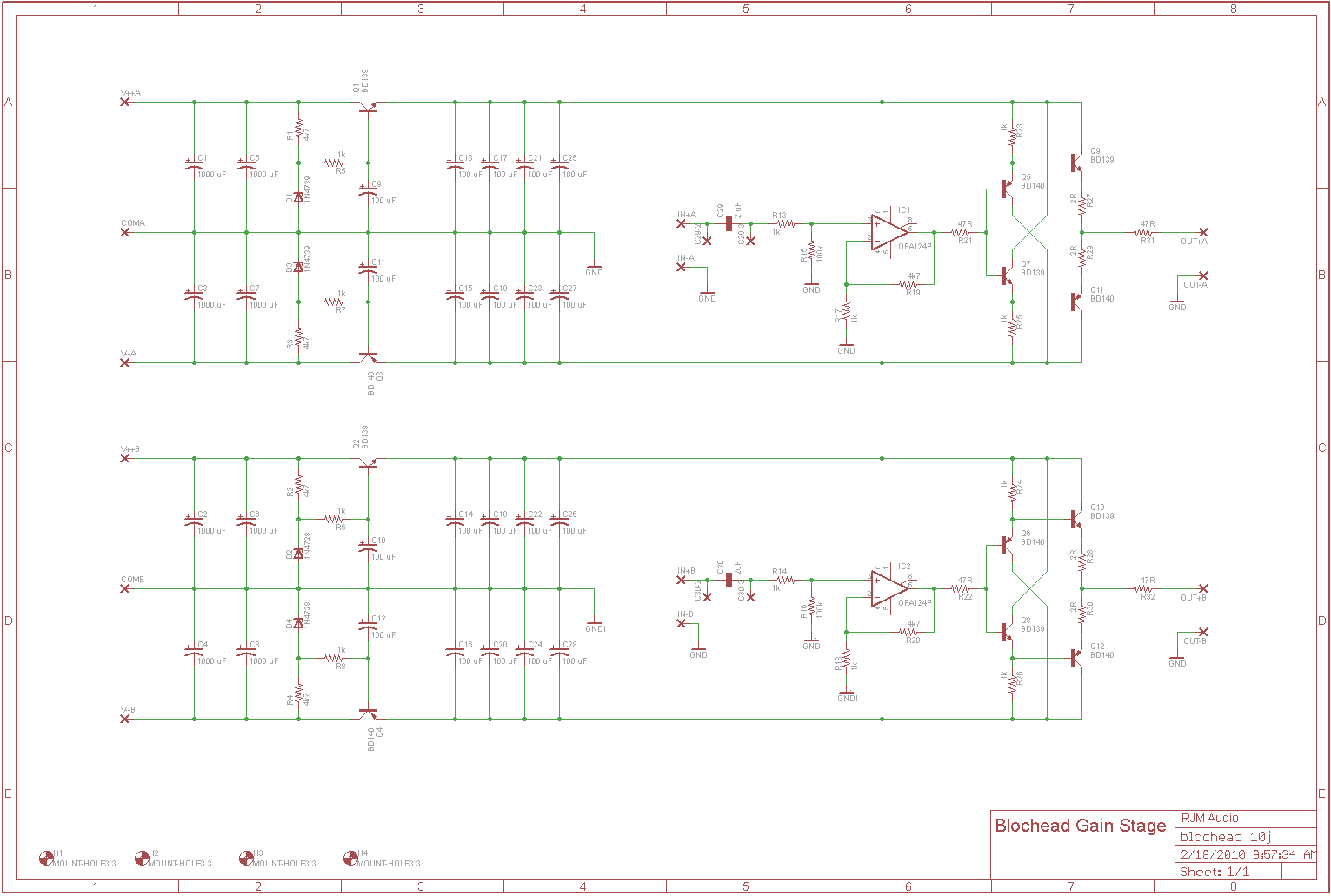
Blochead Diamond Buffer
The circuit is intended to operate with a 100k volume potentiometer and can function as either a line stage or a headphone amplifier. It features a standard non-inverting gain stage with a gain of 15 dB, followed by a discrete...
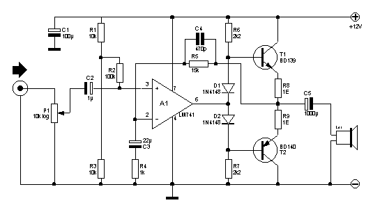
Headphone Amplifier LM741
Here you will find a design for a headphone amplifier. The supply voltage is 12 volts. I have the circuit taken as 5 watt amplifier, but after a test showed that with a little speaker to the amplifier power was...
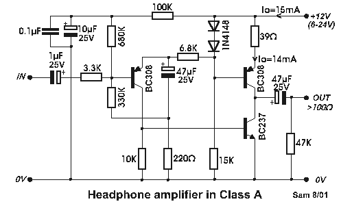
Simple Headphone Amplifier
Even if simple the circuit, plirej' all condition, regarding the distortion and the response of frequency. The resistance of entry is 250K and the load that can drive is between 100R and 2K. The circuit use negative coupling. His exit...
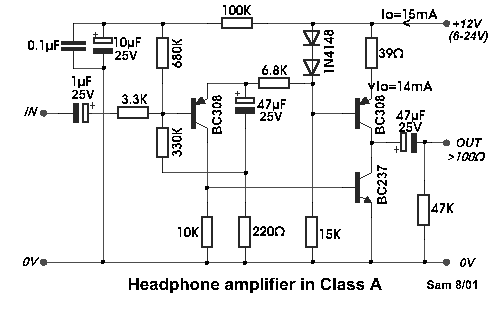
headphone amplifier class a
Even if simple, the circuit meets all conditions regarding distortion and frequency response. The input resistance is 250K ohms, and it can drive loads between 100 ohms and 2K ohms.
The described circuit is a basic signal processing circuit designed to...