


Adding Hazard Indicators Triumph Rat Motorcycle
#hazard indicators
#motorcycle
#flashers
#Bonneville SE
#add-on system
#automotive lighting
#safety
#electrical modification
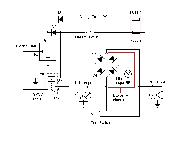
Description: For some time, there has been a desire to incorporate a hazard flasher system into the Bonneville SE. After reviewing various discussions on this topic, a unique add-on system has been developed that functions correctly as hazard lights. This system is designed to be applicable to any vehicle and allows the hazard lights to operate even when the ignition is off. While some may have reservations about this feature, it is considered essential to avoid being stranded in difficult situations, particularly in heavy traffic. The hazard flashers on the car operate without the keys, and the same functionality is desired for the motorcycle. For those uncomfortable with this setup, an alternative option is to wire the hazard switch to a switched supply.
The hazard switch powers a single pole changeover (SPCO) relay, which activates the circuit and switches in the diodes while disconnecting the turn signal switch and supplying power to the flasher unit. The relay, sourced from Maplin Electronics, costs £2.29 (order code N00AW). The diodes selected must be robust enough to manage the total current drawn by all four indicators, calculated as 21W per indicator plus 2.6W for the flasher unit, resulting in a total of 86.6W. This translates to a current of 7.2A at 12V. P600A diodes rated at 6A are sufficient, as each diode in the configuration will handle two lamps, collectively managing 12A. Four P600A diodes are used for the relays, along with two 1N4007 diodes for the modification of the idiot light, which is not detailed in the schematic. The modification involves connecting diode D1 to the orange/green wire from fuse 7 in the fuse box, which originally connects to the flasher relay. This diode prevents other wiring from becoming live when power is supplied to the flasher unit from the hazard switch while the ignition is off, as fuses 7, 8, and 9 are interconnected and powered by the blue/yellow wire from the ignition switch. Similarly, diode D2 prevents the SPCO relay from activating through fuse 7 when the ignition is on.
To enable operation with the ignition off, the hazard switch requires an unswitched power supply. In this case, the wiring for the accessory socket, which is typically left disconnected under the tank, has been utilized. This wiring connects back to fuse 3 in the fuse box (10A). A male Lucar connector was insulated with heat shrink tubing and plugged into the accessory connector block, with the entire assembly wrapped in insulating tape. For those who prefer the hazard lights to function only with the ignition on, the hazard switch can be connected to the orange/green wire instead of the accessory power connector.
Most wiring modifications occur between the two relays. To minimize cutting the wiring harness, the SPCO relay is mounted in place of the flasher relay, while the flasher relay itself is secured to the frame under the seat using a sticky pad. This arrangement requires cutting only two wires in the rear fender harness. The original wiring, which would typically connect to the flasher relay, is redirected to the SPCO relay. A simplified diagram illustrates the actual wiring process: to avoid cutting the flasher relay wiring, the wires are extracted from the flasher relay socket. By using a small screwdriver to release the barb on each connector, the wires can be pulled out from the back and subsequently insulated with heat shrink tubing. The additional wiring can be of any color, and a length of wire is utilized to complete the connections.For a while I have wanted to add a facility for hazard flashers to my Bonneville SE. I have read a couple of threads on this forum about the subject but not found anything which works like hazards should. I have therefore devised my own add-on system, which although is more involved to do compared to those on other threads, is a proper full hazard
system and like the others can be applied to any vehicle. The hazards will work with the ignition off. Some people may not like the idea of this too much, but I for one wouldn`t like to be stranded in an awkward situation, in heavy traffic, where I had to leave the bike to fetch help with the keys in it. My car`s hazard flashers work without the keys in and so should those on my bike. However, if you are not comfortable doing this you can always wire the hazard switch to a switched supply (more on this later).
The hazard switch supplies power to a SPCO (single pole change over) relay, energising it and switching in the diodes, and at the same time switching out the turn signal switch and supplying power to the flasher unit. The relay is from Maplin Electronics and cost £2. 29, order code N00AW. The diodes need to be heavy enough to handle the current drawn by all 4 indicators (21Wx4+2. 6W = 86. 6W. 86. 6W/12V = 7. 2A). P600A diodes rated at 6A are more than adequate since each diode in the pair feeds 2 lamps and collectively will handle 12A.
I used 4 x P600A diodes for the relays and 2 x 1N4007 diodes to modify the idiot light. For clarity the modification to the idiot light is not shown (except on the schematic diagram). This is discussed in another thread: The diode D1 in the diagram has been spliced into the orange/green wire which comes from fuse 7 in the fuse box and goes originally to the flasher relay. This diode prevents other wiring becoming live when power is applied to the flasher unit from the hazard switch while the ignition is off, since fuses 7, 8 and 9 are all linked together in the fuse box and are supplied by the blue/yellow wire from the ignition switch.
Similarly the other diode of the pair, D2, prevents the SPCO relay from activating via fuse 7 when the ignition is on. In order to work with ignition off, the hazard switch needs an unswitched supply. Since I have no accessories and do not plan any, I have used the wiring for the accessory socket, which normally just hangs disconnected under the tank with no insulation - even though it is permanently live.
Nice one Triumph. This wiring goes back to fuse 3 in the fuse box (10A). I made the connection to that by insulating the crimp part of a male Lucar connector with heat shrink tubing and just plugging it into the accessory connector block. The whole thing was then wrapped in insulating tape. Note - If you only want the hazards to work with the ignition on, connect the hazard switch to the orange/green wire instead of the accessory power connector.
Most of the wiring is done between the two relays, so I found the most convenient way, and to avoid cutting the wiring harness wherever possible, was to mount the SPCO relay in place of the Flasher relay, then the Flasher relay was mounted to the frame under the seat with a sticky pad. This way only 2 wires in the rear fender harness need to be cut. The original wiring, which would normally go to the Flasher relay now goes to the SPCO relay. Here is a simpler diagram which shows the actual wiring: To avoid cutting the Flasher relay wiring, the wires are removed from the flasher relay socket.
If you unplug the flasher relay and look at the socket you will see a small square hole by each of the `slots` that the relay blades go into. By inserting a small screwdriver into this hole by each connector and releasing the barb on the connector the wire will pull out from the back.
The connectors are then insulated with a piece of heat shrink tubing. The added wiring can have any colours you like, I used a length of t
The hazard switch powers a single pole changeover (SPCO) relay, which activates the circuit and switches in the diodes while disconnecting the turn signal switch and supplying power to the flasher unit. The relay, sourced from Maplin Electronics, costs £2.29 (order code N00AW). The diodes selected must be robust enough to manage the total current drawn by all four indicators, calculated as 21W per indicator plus 2.6W for the flasher unit, resulting in a total of 86.6W. This translates to a current of 7.2A at 12V. P600A diodes rated at 6A are sufficient, as each diode in the configuration will handle two lamps, collectively managing 12A. Four P600A diodes are used for the relays, along with two 1N4007 diodes for the modification of the idiot light, which is not detailed in the schematic. The modification involves connecting diode D1 to the orange/green wire from fuse 7 in the fuse box, which originally connects to the flasher relay. This diode prevents other wiring from becoming live when power is supplied to the flasher unit from the hazard switch while the ignition is off, as fuses 7, 8, and 9 are interconnected and powered by the blue/yellow wire from the ignition switch. Similarly, diode D2 prevents the SPCO relay from activating through fuse 7 when the ignition is on.
To enable operation with the ignition off, the hazard switch requires an unswitched power supply. In this case, the wiring for the accessory socket, which is typically left disconnected under the tank, has been utilized. This wiring connects back to fuse 3 in the fuse box (10A). A male Lucar connector was insulated with heat shrink tubing and plugged into the accessory connector block, with the entire assembly wrapped in insulating tape. For those who prefer the hazard lights to function only with the ignition on, the hazard switch can be connected to the orange/green wire instead of the accessory power connector.
Most wiring modifications occur between the two relays. To minimize cutting the wiring harness, the SPCO relay is mounted in place of the flasher relay, while the flasher relay itself is secured to the frame under the seat using a sticky pad. This arrangement requires cutting only two wires in the rear fender harness. The original wiring, which would typically connect to the flasher relay, is redirected to the SPCO relay. A simplified diagram illustrates the actual wiring process: to avoid cutting the flasher relay wiring, the wires are extracted from the flasher relay socket. By using a small screwdriver to release the barb on each connector, the wires can be pulled out from the back and subsequently insulated with heat shrink tubing. The additional wiring can be of any color, and a length of wire is utilized to complete the connections.For a while I have wanted to add a facility for hazard flashers to my Bonneville SE. I have read a couple of threads on this forum about the subject but not found anything which works like hazards should. I have therefore devised my own add-on system, which although is more involved to do compared to those on other threads, is a proper full hazard
system and like the others can be applied to any vehicle. The hazards will work with the ignition off. Some people may not like the idea of this too much, but I for one wouldn`t like to be stranded in an awkward situation, in heavy traffic, where I had to leave the bike to fetch help with the keys in it. My car`s hazard flashers work without the keys in and so should those on my bike. However, if you are not comfortable doing this you can always wire the hazard switch to a switched supply (more on this later).
The hazard switch supplies power to a SPCO (single pole change over) relay, energising it and switching in the diodes, and at the same time switching out the turn signal switch and supplying power to the flasher unit. The relay is from Maplin Electronics and cost £2. 29, order code N00AW. The diodes need to be heavy enough to handle the current drawn by all 4 indicators (21Wx4+2. 6W = 86. 6W. 86. 6W/12V = 7. 2A). P600A diodes rated at 6A are more than adequate since each diode in the pair feeds 2 lamps and collectively will handle 12A.
I used 4 x P600A diodes for the relays and 2 x 1N4007 diodes to modify the idiot light. For clarity the modification to the idiot light is not shown (except on the schematic diagram). This is discussed in another thread: The diode D1 in the diagram has been spliced into the orange/green wire which comes from fuse 7 in the fuse box and goes originally to the flasher relay. This diode prevents other wiring becoming live when power is applied to the flasher unit from the hazard switch while the ignition is off, since fuses 7, 8 and 9 are all linked together in the fuse box and are supplied by the blue/yellow wire from the ignition switch.
Similarly the other diode of the pair, D2, prevents the SPCO relay from activating via fuse 7 when the ignition is on. In order to work with ignition off, the hazard switch needs an unswitched supply. Since I have no accessories and do not plan any, I have used the wiring for the accessory socket, which normally just hangs disconnected under the tank with no insulation - even though it is permanently live.
Nice one Triumph. This wiring goes back to fuse 3 in the fuse box (10A). I made the connection to that by insulating the crimp part of a male Lucar connector with heat shrink tubing and just plugging it into the accessory connector block. The whole thing was then wrapped in insulating tape. Note - If you only want the hazards to work with the ignition on, connect the hazard switch to the orange/green wire instead of the accessory power connector.
Most of the wiring is done between the two relays, so I found the most convenient way, and to avoid cutting the wiring harness wherever possible, was to mount the SPCO relay in place of the Flasher relay, then the Flasher relay was mounted to the frame under the seat with a sticky pad. This way only 2 wires in the rear fender harness need to be cut. The original wiring, which would normally go to the Flasher relay now goes to the SPCO relay. Here is a simpler diagram which shows the actual wiring: To avoid cutting the Flasher relay wiring, the wires are removed from the flasher relay socket.
If you unplug the flasher relay and look at the socket you will see a small square hole by each of the `slots` that the relay blades go into. By inserting a small screwdriver into this hole by each connector and releasing the barb on the connector the wire will pull out from the back.
The connectors are then insulated with a piece of heat shrink tubing. The added wiring can have any colours you like, I used a length of t
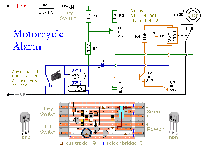
Motorcycle Alarm
The circuit board and switches must be protected from the elements. Dampness or condensation will cause malfunction. Without its terminal blocks, the board is small. Ideally, you should try to find a siren with enough spare space inside to accommodate...
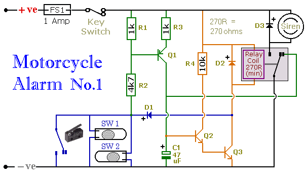
Motorcycle Alarm No.1 - Construction Guide
When one of the normally-open switches is closed, two actions occur. First, the negative side of the relay coil connects to ground through D1, energizing the relay, which in turn activates the siren. Second, the emitter-base junction of Q1 becomes...
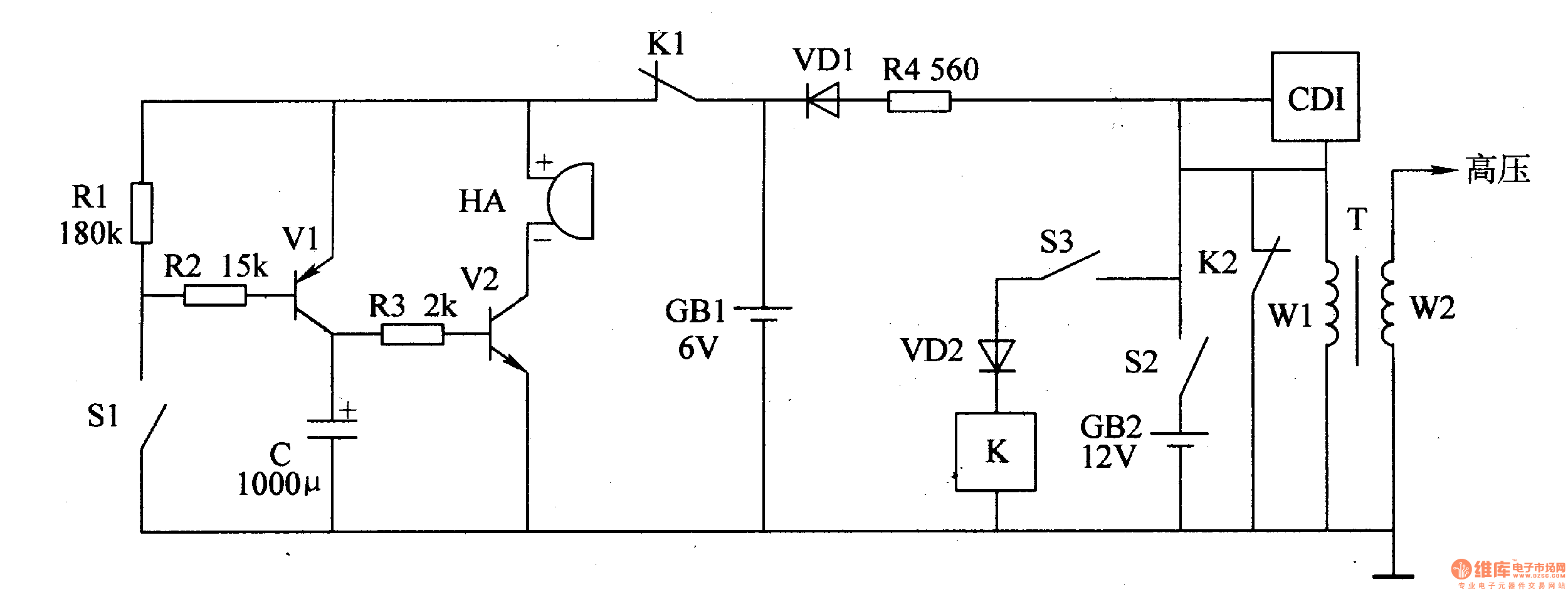
Motorcycle anti-thief alarm circuit (11)
The motorcycle anti-theft alarm circuit consists of a detection alarm circuit, a charging circuit, and an anti-theft control circuit, as illustrated in figure 7-94. The detection alarm circuit includes a mercury switch (S1), resistors (R1-R3), a capacitor (C), transistors (V1,...
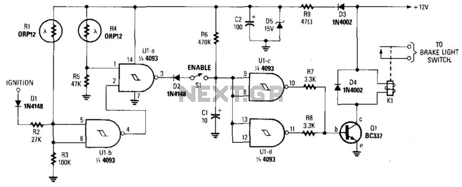
Night Safety Light For Autos
This circuit activates the brake lights of a parked car when headlights from an approaching vehicle are detected, alerting the driver of the oncoming vehicle about the stationary car. LDR4 serves as the sensor, while LDR1 deactivates the circuit by...
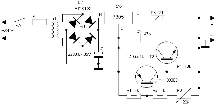
motorcycle battery charger
Motorcycle battery charger power supply. Refer to the mentioned page for an explanation of the power supply related circuit diagram. The description of the battery charger indicator: The circuit above enhances the appearance of a simple battery charger, making it...
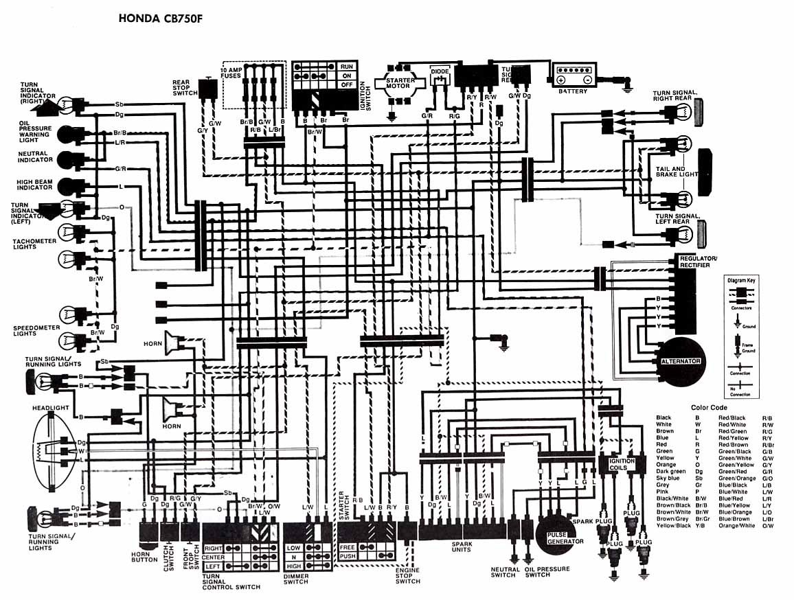
honda motorcycle cb750f ciruit diagram
The following account presents the electrical wiring diagram for the Honda Motorcycle CB750F. It illustrates the connections between various Honda components, including the right turn signal indicator light, oil pressure warning light, neutral indicator, high beam indicator, turn signal indicators,...
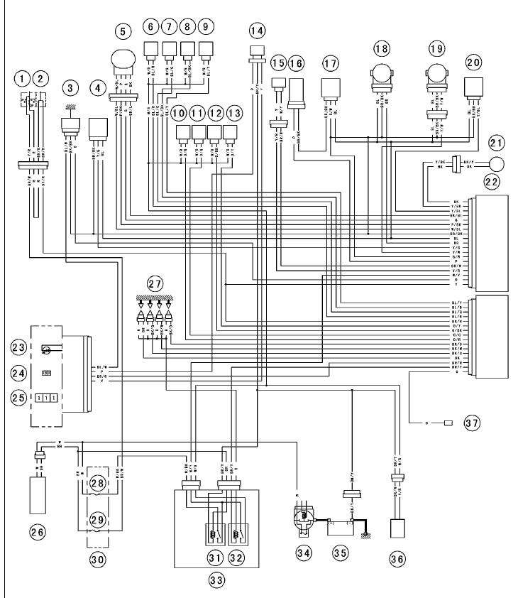
Wiring schematic for 2005 636 Kawasaki
The entire setup was removed from a bike some time ago and functioned properly then. It also operated well approximately a year ago on the engine stand where it is currently mounted. Recently, when attempting to start the engine for...
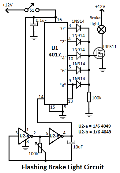
Flashing Brake Light for Motorcycles Circuit
This flashing brake light circuit is designed for motorcycles. When the brake light switch S1 is closed, power is supplied to U1 and U2. The circuit utilizes two inverters from U2.
The flashing brake light circuit operates by utilizing a combination...
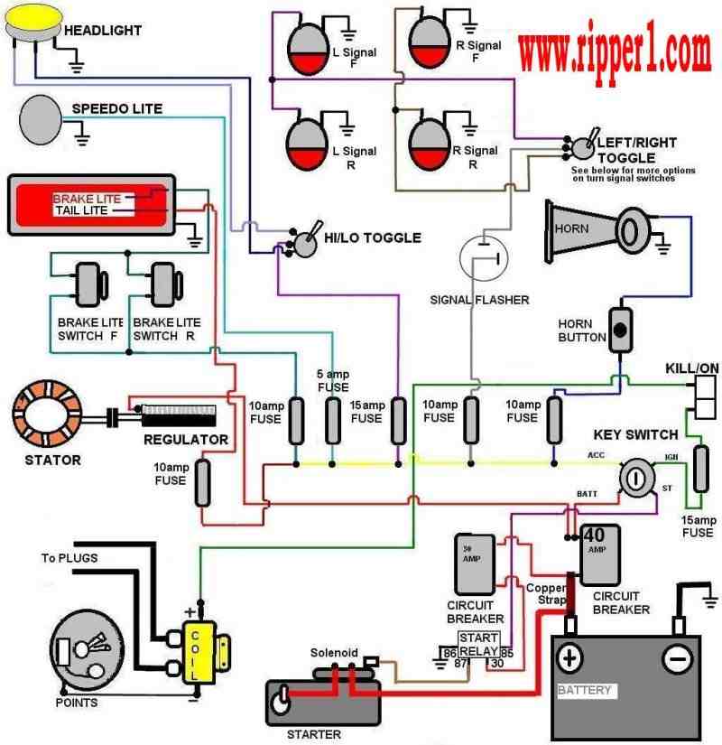
basic motorcycle wiring
Customs by Ripper - A technical page focused on basic wiring for any vehicle, particularly motorcycles.
The page serves as a valuable resource for individuals seeking to understand the fundamentals of vehicle wiring, with a specific emphasis on motorcycles. It...