


Audible Flasher Warning
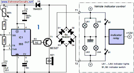
Description: For motorcycle or scooter riders, it is common to forget to deactivate the flashing indicators after making a turn, especially in the absence of an audible reminder.
The circuit for an automatic turn signal cancellation system is designed to address the issue of riders forgetting to turn off their indicators. This system utilizes a combination of sensors, timers, and microcontroller units to ensure that the turn signals are automatically deactivated after a specified duration or upon detecting a change in direction.
The primary components of the circuit include:
1. **Microcontroller**: A microcontroller serves as the central processing unit, receiving input from various sensors and controlling the turn signal lights. It is programmed to monitor the state of the indicators and determine when to deactivate them.
2. **Accelerometer**: An accelerometer is used to detect changes in motion. When the motorcycle or scooter is turned, the accelerometer senses the change in orientation and sends a signal to the microcontroller.
3. **Timer Circuit**: In addition to motion detection, a timer circuit is implemented to provide a backup mechanism for turn signal cancellation. The timer can be set for a specific duration (e.g., 10 seconds) after the indicator is activated, ensuring that the lights turn off automatically if the rider forgets.
4. **Indicator Lights**: The system interfaces with the motorcycle's existing indicator lights, allowing for seamless integration without requiring extensive modifications.
5. **Power Supply**: The circuit is powered by the motorcycle’s battery, ensuring it operates reliably without the need for additional power sources.
The design must consider factors such as power consumption, environmental resilience, and the ability to operate under various riding conditions. Proper calibration of the accelerometer and timer settings is crucial to ensure that the turn signals deactivate at the appropriate moments, enhancing safety and convenience for riders.
Overall, this automatic turn signal cancellation system significantly improves rider awareness and safety by reducing the likelihood of leaving indicators activated unintentionally.If you re a biker or scooter rider you ll know how easy it is to forget to cancel your flashing indicators after turning without an audible reminder. Cons..
The circuit for an automatic turn signal cancellation system is designed to address the issue of riders forgetting to turn off their indicators. This system utilizes a combination of sensors, timers, and microcontroller units to ensure that the turn signals are automatically deactivated after a specified duration or upon detecting a change in direction.
The primary components of the circuit include:
1. **Microcontroller**: A microcontroller serves as the central processing unit, receiving input from various sensors and controlling the turn signal lights. It is programmed to monitor the state of the indicators and determine when to deactivate them.
2. **Accelerometer**: An accelerometer is used to detect changes in motion. When the motorcycle or scooter is turned, the accelerometer senses the change in orientation and sends a signal to the microcontroller.
3. **Timer Circuit**: In addition to motion detection, a timer circuit is implemented to provide a backup mechanism for turn signal cancellation. The timer can be set for a specific duration (e.g., 10 seconds) after the indicator is activated, ensuring that the lights turn off automatically if the rider forgets.
4. **Indicator Lights**: The system interfaces with the motorcycle's existing indicator lights, allowing for seamless integration without requiring extensive modifications.
5. **Power Supply**: The circuit is powered by the motorcycle’s battery, ensuring it operates reliably without the need for additional power sources.
The design must consider factors such as power consumption, environmental resilience, and the ability to operate under various riding conditions. Proper calibration of the accelerometer and timer settings is crucial to ensure that the turn signals deactivate at the appropriate moments, enhancing safety and convenience for riders.
Overall, this automatic turn signal cancellation system significantly improves rider awareness and safety by reducing the likelihood of leaving indicators activated unintentionally.If you re a biker or scooter rider you ll know how easy it is to forget to cancel your flashing indicators after turning without an audible reminder. Cons..
Power Flashers
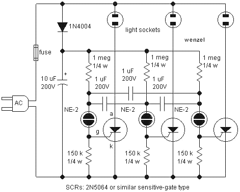
A simple circuit for sequentially flashing Christmas light strings or other similar low-power lamps. The socket symbols may represent single bulbs or sockets for lamp strings. The load must operate from DC since the SCRs rectify the line voltage. The...
Micro Flasher
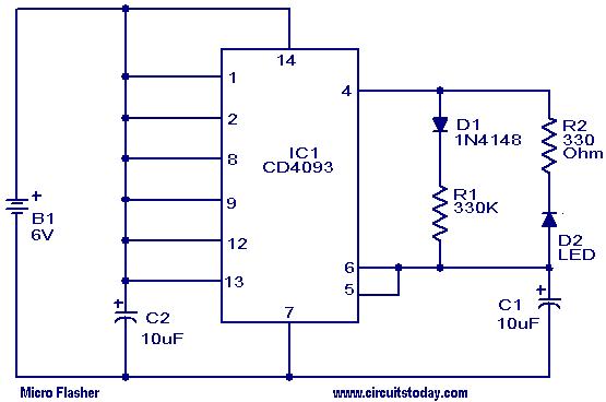
This micro flasher circuit continuously emits a flashing light while consuming very little power. The circuit can operate for an extended period using four 1.5V torch cells. A low-power CMOS IC, the CD4093 (IC1), is utilized to generate sharp pulses...
Night Safety Light For Autos
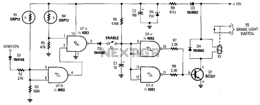
This circuit activates the brake lights of a parked car when headlights from an approaching vehicle are detected, alerting the driver of the oncoming vehicle about the stationary car. LDR4 serves as the sensor, while LDR1 deactivates the circuit by...
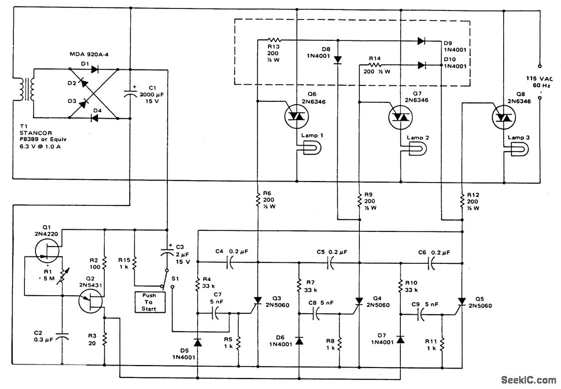
SEQUENTIAL AC FLASHER
This circuit utilizes a ring counter consisting of Q3, Q4, and Q5. Q2 functions as an oscillator that sequentially triggers the SCRs Q3, Q4, and Q5. When an SCR is activated, a 0.2 F capacitor facilitates commutation, turning off the...

Mini Flasher
This is a simple and compact flasher circuit that can be used wherever a flashing LED is needed. The circuit is applicable in flashing beacons, alarms, automobiles, and more. It is essentially an astable multivibrator based on the NE555 integrated...
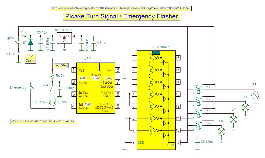
Flasher circuit negative switching
Access to the resistors was available, and measurements indicated an open circuit when disconnected from any ground or input source.
The circuit in question involves resistors that have been verified for accessibility. When measured in isolation—meaning they are not connected to...
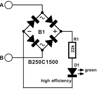
indicator circuit
The modem off indicator is designed specifically for avid Internet users. The circuit for this indicator is remarkably simple, and its simplicity may lead to significant cost savings by providing a clear visual indication of whether the telephone line is...
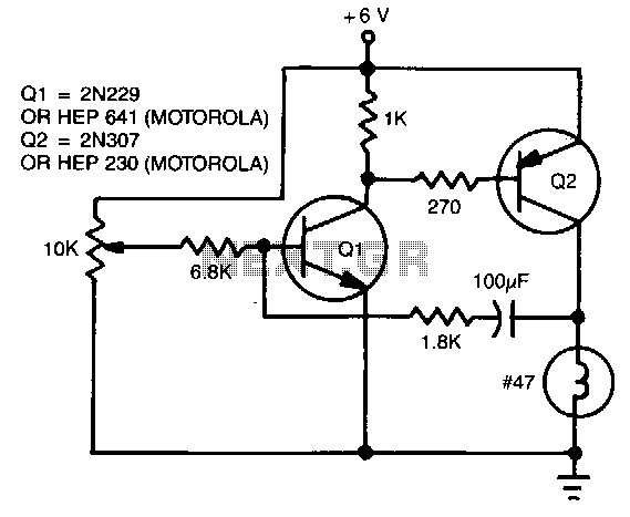
Single-lamp-flasher
The flash rate is controlled by a complementary multivibrator consisting of an NPN and a PNP transistor.
The complementary multivibrator circuit is a fundamental electronic configuration used to generate square wave signals, which can be employed for various applications including flashing...
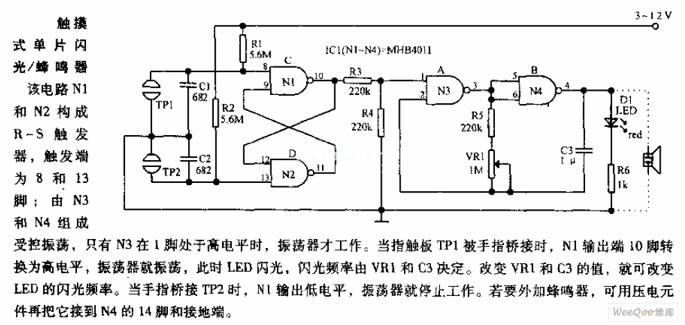
Touching monolithic flasher - buzzer circuit diagram
In the circuit, N1 and N2 form the RS flip-flop, with the trigger inputs located at pins 8 and 13. N3 and N4 create a controlled oscillator that operates only when pin 1 of N3 is high. When the finger...