


Automatic reclosing device program Control Ladder
#PLC
#automatic reclosing
#control program
#ladder logic
#industrial automation
#motor control
#safety
#electrical engineering
#programmable logic
#device control
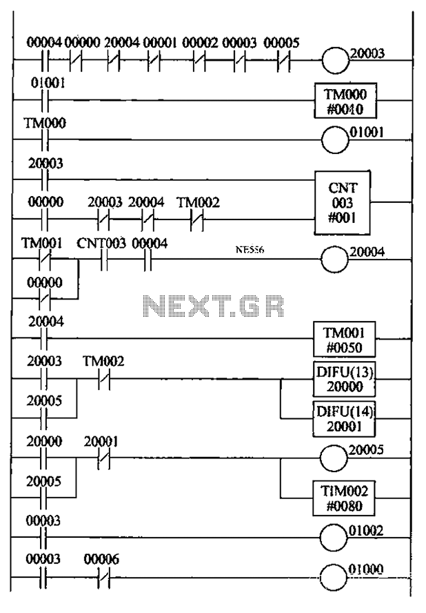
Description: An automatic reclosing PLC control program has been developed based on the specifications for automatic reclosing devices and PLC I/O definitions. The design includes a ladder-shaped diagram with the following features: 1) When the circuit breaker closes, the K4 control switch is activated, closing contact point 00004. The auxiliary contacts of the DL Liha breaker, which are normally closed, disconnect contact 00000. In the event of a line failure, the circuit breaker trips, causing the auxiliary contacts DL F-off to close contact 00000, energizing coil 20003 and closing the normally closed contacts to initiate timer TIMO00. After a specified delay, coil 01001 is energized to close. 2) If the automatic reclosing is successful after the delay from TIMO01, the normally closed contacts TIMO01 disconnect the line power to ring 20004, which then closes its normally closed contact, allowing the automatic reclosing device to reset. 3) If the reclosing is unsuccessful after a predetermined number of attempts, coil 20003 is energized due to the timer TIMO01, while coil 20004 remains energized. The normally closed contact 20004 opens, breaking the circuit for coil 20003. As the circuit breaker remains tripped, the normally closed contact 00000 stays closed, maintaining the energization of coil 20004, preventing further reclosing attempts. 4) The operation control switch K is activated, energizing node K4 and coil 20004 for manual reset. 5) The ladder instruction selection counter CNT is set to match the predetermined number of reclosing attempts, while TIMO00 manages the timing of automatic operations. The reset time for automatic reclosing is controlled by the rising and falling edges of the differential instruction DIFU (13) and DIFU (14), combined with timer instruction TIM002, to ensure that the counter CNT resets appropriately to complete the required number of automatic reclosing attempts. 6) In a manual operation where the circuit breaker trips, K1 and K2 are activated, opening normally closed contacts 00001 and 00002 to ensure coil 20003 is not energized, thereby locking out automatic reclosing. 7) The manual trip process is initiated with K3, which disconnects normally closed contact 00003, locking out reclosing. The normally open contacts close, energizing coil 01002 to trigger the relay for the trip circuit. 8) If the circuit breaker experiences insufficient hydraulic pressure, switches SQ1 and 9Q2 cannot be pressed simultaneously, causing normally open contact 00005 to open, which locks out the automatic reclosing circuit. Normally closed contact 00006 closes, energizing coil 01000, which is connected in series to the trip circuit, opening the latch for the trip circuit.
This case study addresses the limitations of traditional automatic reclosing relay systems by introducing a PLC-based design for automatic reclosing. The hardware implementation features straightforward and reliable wiring, while the software not only fulfills the control functions of the automatic reclosing device but also integrates PLC counters, timers, and other instructions. This design allows for the adjustment of delay times and the automatic resetting of the system, enhancing the control and flexibility of the pump system, and demonstrating versatility and practicality in operation. The overall architecture provides a robust solution for managing circuit breaker operations with a focus on safety, reliability, and responsiveness to operational conditions. Automatic reclosing PLC control program designed according to the Control of automatic reclosing device and the PLC I/o definition, design ladder -shaped diagram as follows: 1) when the circuit breaker closing, K4 control switch is turned on, its contact point is closed 00004. DL Liha breaker auxiliary contacts, the normally closed contact 00000 disconnected. When the line fails, the circuit breaker jump gates, auxiliary contacts DL F-off, the normally closed contact is closed 00000, 20003 coil is energized, the normally closed contacts are closed, the timer TIMOOO work.
After a delay. 01001 coil is energized and closing. 2) If the automatic reclosing successful closing by the delay TIMO01, the normally closed contacts TIMO01 disconnect line power ring 20004, 20004 closes its normally closed contact, automatic reclosing devices automatically reset. 3) If the closing is not successful, complete reclosing predetermined times after the number 20003 coil is energized, due to the delay TIMO01 make with coil 20004 is still energized, the normally closed contact 20004 is broken open state, coil break 20003 Electricity.
And because a circuit breaker trip state where the normally closed contact 00000 closed, self-holding role to play, so that the coil has been energized 20004, reclosing can not be achieved again. 4) the operation control switch K is turned on so that the node K4. 20004 coil is energized, for manual reset. 5) Ladder instruction selection counter CNT is set from reclosing predetermined number of times coincide, TIMOOO automatic coincidence gate resistance movements extended time.
TIMO01 automatic reclosing reset time. By the rising and falling edges of the differential instruction DIFU differential (13) and DIFU (14) and the timer instruction TIM002 combination, to achieve a delay counter CNT is reset to ensure autoreclosure complete the required number of times coincide. 6) manually operated circuit breaker trip process, Kl, K2 is turned on, the respective normally closed contacts open 00001,00002 ensure coil 20003 is not energized, the automatic reclosing lockout circuit.
7) manually operated circuit breaker trip process. K3 connected to the normally closed contact 00003 off, reclosing lockout circuit. 00003 normally open contacts closed, the coil is energized 01002, turn accelerated relay trip circuit. 8) When the circuit breaker or insufficient hydraulic pressure, SQ1,9Q2 switch can not be pressed together, the normally open contact 00005 open, automatic reclosing lockout circuit.
Normally closed contact 00006 closes, 01000 electric coil, connected in series in the trip circuit contacts open, the latch trip circuit. (4) Conclusion This case study of the traditional automatic reclosing relay apparatus shortcomings exist, PLC-based design of automatic reclosing.
The design, the hardware has installed wiring is simple, reliable; on the software, not only to meet the group automatic reclosing device of this control function, but also the application of PLC counters, timers and other instructions to achieve automatic reclosing overlap times required to adjust the delay time and automatically reset the system to improve the control and flexibility of the pump system has the versatility and practicality.
This case study addresses the limitations of traditional automatic reclosing relay systems by introducing a PLC-based design for automatic reclosing. The hardware implementation features straightforward and reliable wiring, while the software not only fulfills the control functions of the automatic reclosing device but also integrates PLC counters, timers, and other instructions. This design allows for the adjustment of delay times and the automatic resetting of the system, enhancing the control and flexibility of the pump system, and demonstrating versatility and practicality in operation. The overall architecture provides a robust solution for managing circuit breaker operations with a focus on safety, reliability, and responsiveness to operational conditions. Automatic reclosing PLC control program designed according to the Control of automatic reclosing device and the PLC I/o definition, design ladder -shaped diagram as follows: 1) when the circuit breaker closing, K4 control switch is turned on, its contact point is closed 00004. DL Liha breaker auxiliary contacts, the normally closed contact 00000 disconnected. When the line fails, the circuit breaker jump gates, auxiliary contacts DL F-off, the normally closed contact is closed 00000, 20003 coil is energized, the normally closed contacts are closed, the timer TIMOOO work.
After a delay. 01001 coil is energized and closing. 2) If the automatic reclosing successful closing by the delay TIMO01, the normally closed contacts TIMO01 disconnect line power ring 20004, 20004 closes its normally closed contact, automatic reclosing devices automatically reset. 3) If the closing is not successful, complete reclosing predetermined times after the number 20003 coil is energized, due to the delay TIMO01 make with coil 20004 is still energized, the normally closed contact 20004 is broken open state, coil break 20003 Electricity.
And because a circuit breaker trip state where the normally closed contact 00000 closed, self-holding role to play, so that the coil has been energized 20004, reclosing can not be achieved again. 4) the operation control switch K is turned on so that the node K4. 20004 coil is energized, for manual reset. 5) Ladder instruction selection counter CNT is set from reclosing predetermined number of times coincide, TIMOOO automatic coincidence gate resistance movements extended time.
TIMO01 automatic reclosing reset time. By the rising and falling edges of the differential instruction DIFU differential (13) and DIFU (14) and the timer instruction TIM002 combination, to achieve a delay counter CNT is reset to ensure autoreclosure complete the required number of times coincide. 6) manually operated circuit breaker trip process, Kl, K2 is turned on, the respective normally closed contacts open 00001,00002 ensure coil 20003 is not energized, the automatic reclosing lockout circuit.
7) manually operated circuit breaker trip process. K3 connected to the normally closed contact 00003 off, reclosing lockout circuit. 00003 normally open contacts closed, the coil is energized 01002, turn accelerated relay trip circuit. 8) When the circuit breaker or insufficient hydraulic pressure, SQ1,9Q2 switch can not be pressed together, the normally open contact 00005 open, automatic reclosing lockout circuit.
Normally closed contact 00006 closes, 01000 electric coil, connected in series in the trip circuit contacts open, the latch trip circuit. (4) Conclusion This case study of the traditional automatic reclosing relay apparatus shortcomings exist, PLC-based design of automatic reclosing.
The design, the hardware has installed wiring is simple, reliable; on the software, not only to meet the group automatic reclosing device of this control function, but also the application of PLC counters, timers and other instructions to achieve automatic reclosing overlap times required to adjust the delay time and automatically reset the system to improve the control and flexibility of the pump system has the versatility and practicality.
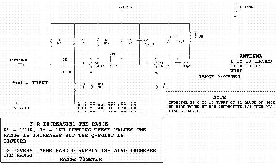
motor timer
The primary concept is to rotate the motor slightly every 15 seconds. A monofilament line conveys the motion to the ornament, which is wound by the motor and gradually unwinds as the ornament turns. The charging circuit includes a 1...
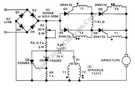
Series-Wound Direction And Speed Motor Control
This is a motor controller circuit that controls the speed and direction of series-wound motors. This circuit employs silicon controlled rectifiers (SCR).
The motor controller circuit is designed to manage both the speed and direction of series-wound motors, which are commonly...
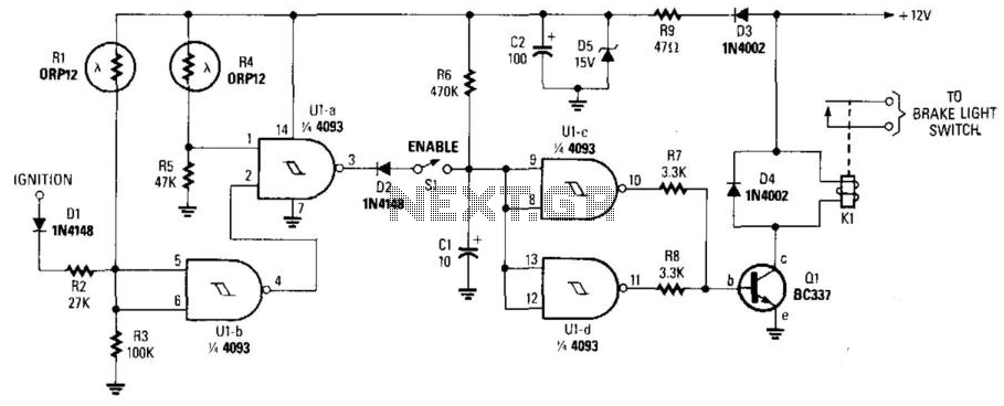
Night Safety Light For Autos
This circuit activates the brake lights of a parked car when headlights from an approaching vehicle are detected, alerting the driver of the oncoming vehicle about the stationary car. LDR4 serves as the sensor, while LDR1 deactivates the circuit by...
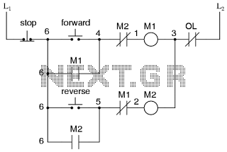
Motor control circuit for forward and reverse phase induction
This is the power diagram for motor forward and reverse operation. To change the motor direction, one polarity must be altered, for example, changing R to S. For detailed information, please refer to the following.
The described power diagram illustrates a...
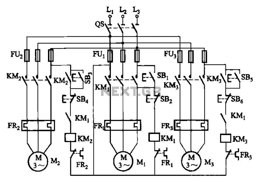
Three motor control circuit start and stop sequence requirements
The circuit shown in Figure 3-89 illustrates a system where starting motor M1 allows motors M2 and M3 to initiate operation. Upon shutdown, motor Mz can be stopped first; however, once motor M1 is stopped (by pressing switch SB2), motors...
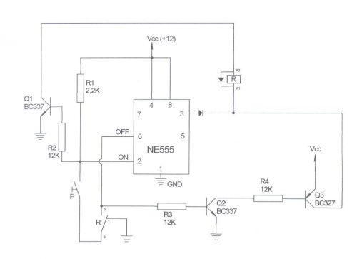
PLC andCircuits
This site addresses a range of subjects pertaining to circuits and electronics. Some of the topics discussed on this site include: * Alternating Relay Switch * Photoswitch Relay.
The site serves as a comprehensive resource for understanding various electronic components and...
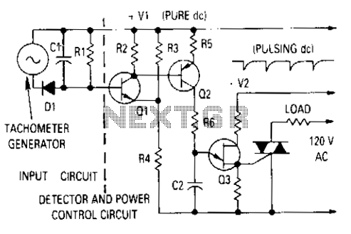
Motor control with tachometer
The generator output is rectified, filtered, and applied between the positive supply voltage and the base of the detector transistor. This configuration provides a negative voltage that reduces the base voltage as the speed increases. During normal operation, if the...
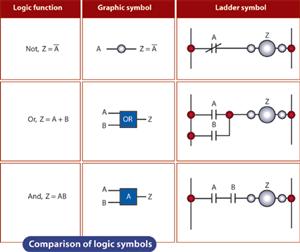
basics ladder logic
The ladder logic programming method is a widely utilized approach in the programming of electrical simulation schematic control systems. This method primarily serves to make decisions regarding whether specific load circuits should be opened or closed. To comprehend ladder logic,...
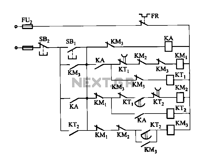
2 -Y- connection automatic three-speed motor acceleration control circuit
Figure 3-118 illustrates an automatic acceleration control circuit. This circuit employs a male contactor time relay, enabling the motor to start automatically at a low speed before transitioning to high-speed operation.
The automatic acceleration control circuit depicted in Figure 3-118 is...