


Automatic Wiper Control Circuit using NE 555 IC
#NE 555
#wiper control
#car
#motor speed control
#intermittent
#windshield
#timer
#automotive electronics
#sweep rate
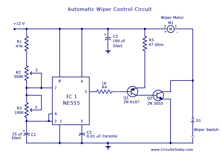
Description: A circuit for car windshield/wiper motor speed control built using an NE 555 IC. This enables intermittent windshield wiper control, which changes the sweep rate to 10 seconds.
The circuit utilizes the NE 555 timer IC configured in astable mode to control the operation of a windshield wiper motor. The primary function of this circuit is to provide an adjustable intermittent wipe feature, allowing the wipers to operate at a set interval, specifically every 10 seconds.
In this design, the NE 555 generates a square wave output that drives a transistor, which acts as a switch for the wiper motor. The frequency of the square wave is determined by the values of two resistors (R1 and R2) and a capacitor (C1) connected to the 555 timer. The duty cycle can be adjusted by varying the resistance values, which in turn changes the time the wipers are on and off.
The circuit is powered by the vehicle’s battery, typically at 12V, and includes components such as diodes for flyback protection to prevent back EMF from damaging the circuit when the motor is turned off. Additionally, a potentiometer may be included in the circuit to allow for fine-tuning of the delay interval based on user preference.
This design not only enhances the functionality of the windshield wipers but also contributes to safer driving conditions during inclement weather by ensuring optimal visibility through controlled wiper operation.A circuit for car windshield/wiper motor speed control built using NE 555 IC.This enables intermittent windshield wiper control which changes sweep rate to 10 seconds..
The circuit utilizes the NE 555 timer IC configured in astable mode to control the operation of a windshield wiper motor. The primary function of this circuit is to provide an adjustable intermittent wipe feature, allowing the wipers to operate at a set interval, specifically every 10 seconds.
In this design, the NE 555 generates a square wave output that drives a transistor, which acts as a switch for the wiper motor. The frequency of the square wave is determined by the values of two resistors (R1 and R2) and a capacitor (C1) connected to the 555 timer. The duty cycle can be adjusted by varying the resistance values, which in turn changes the time the wipers are on and off.
The circuit is powered by the vehicle’s battery, typically at 12V, and includes components such as diodes for flyback protection to prevent back EMF from damaging the circuit when the motor is turned off. Additionally, a potentiometer may be included in the circuit to allow for fine-tuning of the delay interval based on user preference.
This design not only enhances the functionality of the windshield wipers but also contributes to safer driving conditions during inclement weather by ensuring optimal visibility through controlled wiper operation.A circuit for car windshield/wiper motor speed control built using NE 555 IC.This enables intermittent windshield wiper control which changes sweep rate to 10 seconds..
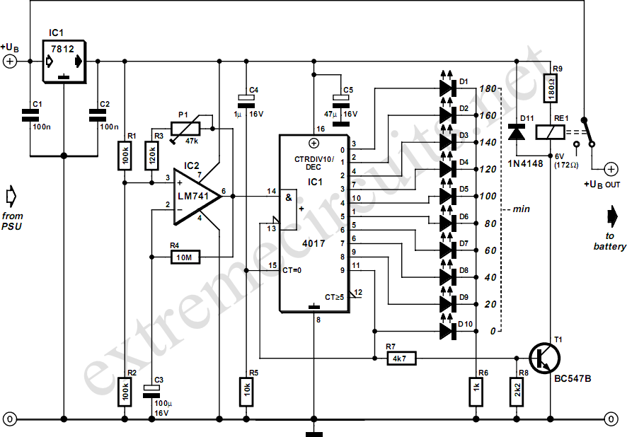
Three Hour Timer
Manufacturers of cordless drills typically recommend a battery charging time of three hours. Once this charging time is complete, the battery must be disconnected from the charger to prevent the risk of overcharging. This circuit, positioned between the charger and...
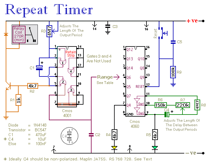
repeating interval timer
This circuit features an adjustable output timer that can re-trigger at regular intervals. The output duration can range from a fraction of a second to over half an hour, with the ability to recur at intervals from seconds to days....
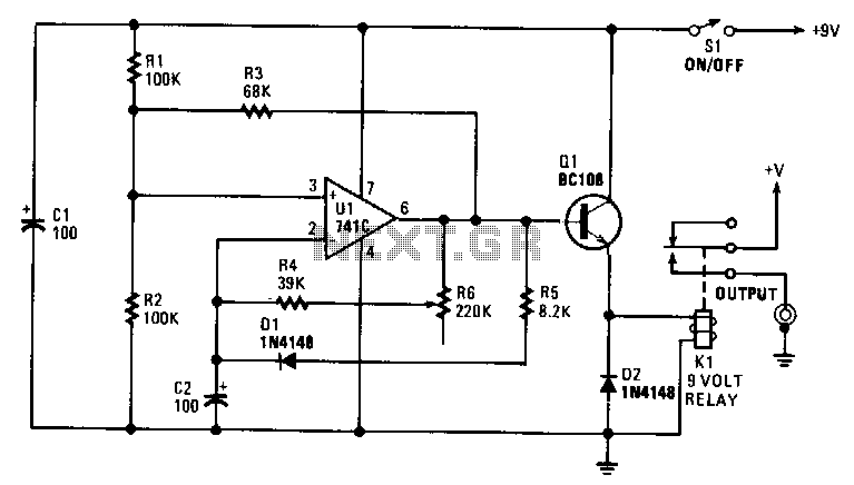
Slide-show-timer
The interval can be set between approximately 5 to 30 seconds. A relay controls the slide-change mechanism. Operational amplifier U1 functions as a type of Schmitt trigger. Resistors R1 and R2 bias the non-inverting input at pin 3 of U1...
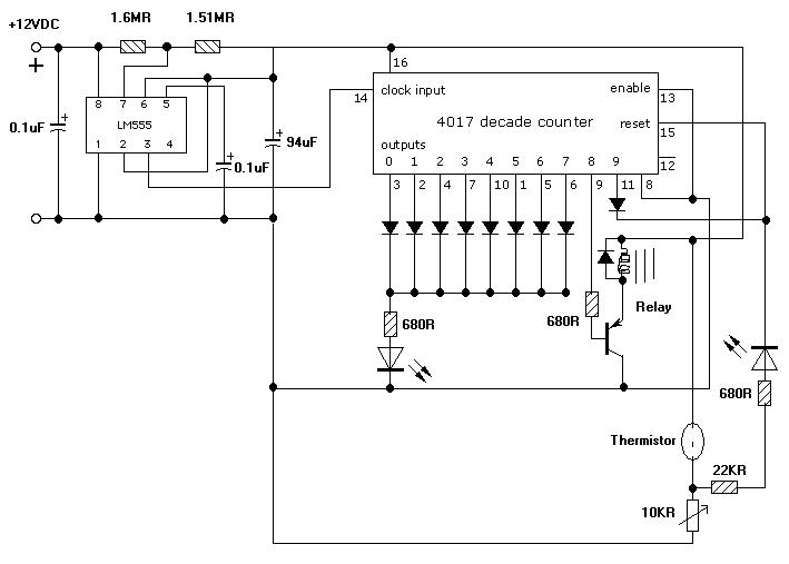
Timer Circuit
I am looking to build a timer for a pump. I want the pump to run for 5 minutes, then stop.
To create a timer circuit for a pump that operates for a duration of 5 minutes, a simple astable multivibrator...
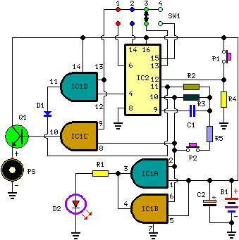
A Very Useful Timed Beeper Circuit Schematic
This circuit is designed for alerting purposes after a specified duration has elapsed. It is suitable for table games that require a fixed time limit to answer a question or to move a piece, serving as a modern substitute for...
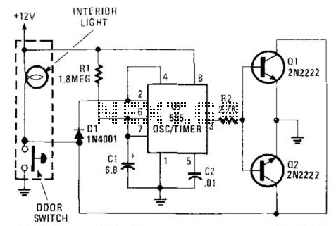
Interior Convenience Light
When the door is closed, this circuit maintains the dome light illumination for a duration determined by the values of R1 and C1. The approximate time is given by the equation (1.1)R1 x C1.
The described circuit functions as a timer...
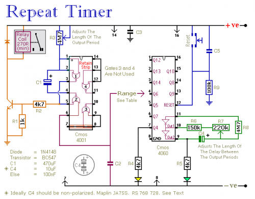
A Regularly Repeating Interval Timer
This circuit features an adjustable output timer capable of re-triggering at regular intervals. The output duration can range from a fraction of a second to half an hour or longer, with the ability to recur at intervals spanning from seconds...
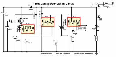
Timer Garage Door Circuit Schematic Diagram
Timer garage door circuit schematic diagram, printed circuit board.
The timer garage door circuit is designed to automate the opening and closing of a garage door based on a predetermined time interval. The schematic diagram illustrates the layout and connections of...
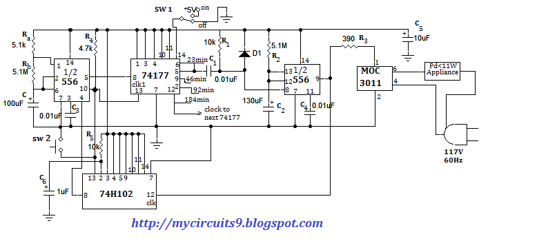
APPLIANCE CONTROL USING TIMER - PROJECT
This document presents an electronic project focused on device control using a timer. This circuit allows for the activation of an appliance at a specified time for a predetermined duration. It can be applied to manage the operation of systems...