


Automobile-air-conditioner
#air conditioner
#engine power
#vacuum sensor
#compressor clutch
#delay circuit
#automotive safety
#intake manifold
#load management
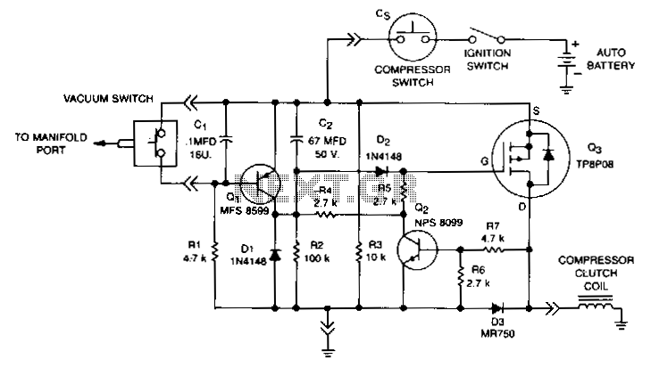
Description: This circuit disables the air conditioner compressor when additional engine power is required. It does so by monitoring the engine vacuum at the intake manifold. If the vacuum drops to 40% of its normal level, the compressor clutch is disabled, removing the air conditioner load from the engine. After the engine returns to the normal vacuum level, there is a 6-second delay before the compressor clutch is enabled again, reactivating the air conditioner. This allows for an additional 6 seconds of power, approximately 500 feet at 60 MPH, which increases the safety margin when passing another vehicle. The loss of cooling is minimal because the air conditioner fan continues to operate. When the engine accelerates, manifold vacuum decreases, causing vacuum switch VS to open at 40% of the normal manifold pressure. This action turns on transistor Q1, discharging capacitor C2 and turning off transistor Q3 via diode D2. When Q3 turns off, transistor Q2 also turns off. Once the engine reaches its normal operating vacuum, vacuum switch VS closes, turning off Q1 and allowing capacitor C2 to charge for 6 seconds until Q3 is activated again.
The circuit operates primarily through a feedback mechanism that utilizes a vacuum switch (VS) to monitor the engine's intake manifold pressure. The threshold level is set at 40% of the normal vacuum, which is a critical point where the engine requires additional power, typically during acceleration or when under load. When the vacuum switch detects this drop, it activates transistor Q1, which plays a pivotal role in controlling the discharge of capacitor C2. The discharge of C2 results in the deactivation of transistor Q3, which subsequently disables the compressor clutch.
The delay mechanism is essential for maintaining a balance between performance and comfort. By incorporating a 6-second delay after the vacuum returns to normal levels, the circuit ensures that the air conditioning system does not reactivate instantaneously, which could lead to a sudden increase in load on the engine. This feature allows for a smoother transition back to normal operating conditions, ensuring that the engine can maintain optimal performance without the burden of the air conditioning load.
Moreover, the design minimizes the impact on cooling performance. The air conditioning fan remains operational, providing continuous airflow and mitigating any significant loss of cooling during the brief period when the compressor is disabled. The use of diode D2 ensures that the control signals are directed appropriately, preventing any unwanted feedback that could lead to erratic behavior in the circuit.
Overall, this circuit design effectively enhances vehicle performance during critical driving situations while maintaining passenger comfort, illustrating a well-thought-out approach to automotive electronic control systems.This circuit disables the air conditioner compressor when additional engine power is required. It does so by monitoring the engine vacuum at the intake manifold. Ifthe vacuum drops to 40% of its normal level, the compressor clutch is disabled, removing the air conditioner load from the engine. After the engine returns to normal vacuum level, there is a 6 second delay before the compressor clutch is enabled and the air conditioner is reactivated.
This allows 6 seconds of extra power, about 500 ft at 60 MPH, which increases the safety margin when passinganother vehicle. Loss of cooling is minimal because the air conditioner fan is not interrupted. When the engine is accelerated, manifold vacuum drops and vacuum switch VS opens to 40% of the normal manifold pressure. This causes Ql to turn on, discharging C2 and turning off Q3 via diode D2. When Q3 turns off, sn does Q2. When the engine reaches its normal operating vacuum, VS closes and Ql turns off, allowing C2 to charge for 6 seconds until Q3 turns on again.
The circuit operates primarily through a feedback mechanism that utilizes a vacuum switch (VS) to monitor the engine's intake manifold pressure. The threshold level is set at 40% of the normal vacuum, which is a critical point where the engine requires additional power, typically during acceleration or when under load. When the vacuum switch detects this drop, it activates transistor Q1, which plays a pivotal role in controlling the discharge of capacitor C2. The discharge of C2 results in the deactivation of transistor Q3, which subsequently disables the compressor clutch.
The delay mechanism is essential for maintaining a balance between performance and comfort. By incorporating a 6-second delay after the vacuum returns to normal levels, the circuit ensures that the air conditioning system does not reactivate instantaneously, which could lead to a sudden increase in load on the engine. This feature allows for a smoother transition back to normal operating conditions, ensuring that the engine can maintain optimal performance without the burden of the air conditioning load.
Moreover, the design minimizes the impact on cooling performance. The air conditioning fan remains operational, providing continuous airflow and mitigating any significant loss of cooling during the brief period when the compressor is disabled. The use of diode D2 ensures that the control signals are directed appropriately, preventing any unwanted feedback that could lead to erratic behavior in the circuit.
Overall, this circuit design effectively enhances vehicle performance during critical driving situations while maintaining passenger comfort, illustrating a well-thought-out approach to automotive electronic control systems.This circuit disables the air conditioner compressor when additional engine power is required. It does so by monitoring the engine vacuum at the intake manifold. Ifthe vacuum drops to 40% of its normal level, the compressor clutch is disabled, removing the air conditioner load from the engine. After the engine returns to normal vacuum level, there is a 6 second delay before the compressor clutch is enabled and the air conditioner is reactivated.
This allows 6 seconds of extra power, about 500 ft at 60 MPH, which increases the safety margin when passinganother vehicle. Loss of cooling is minimal because the air conditioner fan is not interrupted. When the engine is accelerated, manifold vacuum drops and vacuum switch VS opens to 40% of the normal manifold pressure. This causes Ql to turn on, discharging C2 and turning off Q3 via diode D2. When Q3 turns off, sn does Q2. When the engine reaches its normal operating vacuum, VS closes and Ql turns off, allowing C2 to charge for 6 seconds until Q3 turns on again.
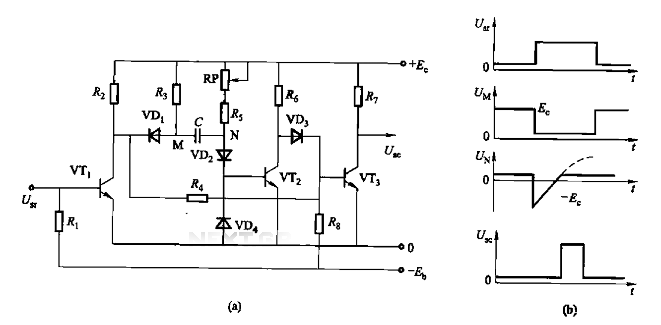
As control the discharge tube type delay circuit
The circuit described is a discharge delay circuit that offers a longer delay compared to a standard rechargeable delay circuit, while also maintaining relatively high accuracy. The schematic diagram illustrates the input and output waveforms. Typically, when there is no...
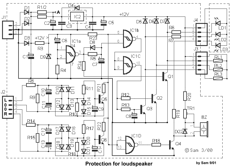
DC Protection Time Delay for Loudspeaker circuit
The circuit integrates several functions, including a smooth startup for the AC power line, with a one-second delay before connecting to the power supply transformers of the amplifier through relay RL1 and resistor Rx. This delay is designed to prevent...
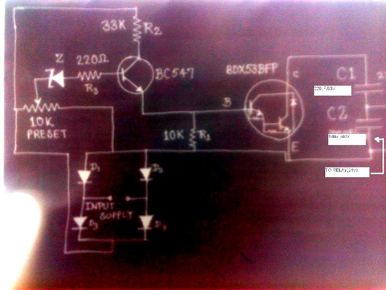
make this simple delay on circuit
The post discusses a simple delay ON circuit that enables a connected load to be powered on with a predetermined delay after the power switch is activated. This circuit is applicable for any scenario that requires an initial delay before...
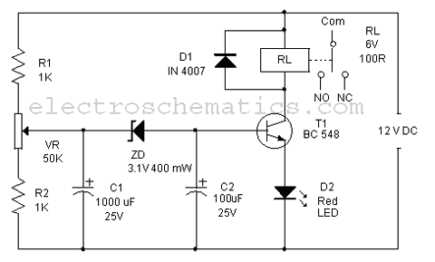
Delay On Circuit
Protect your LCD or Plasma TV with this small delay-on circuit. The SMPS-based power supply of these modern electronic devices is susceptible to voltage spikes.
This delay-on circuit is designed to enhance the protection of LCD and Plasma TVs by mitigating...

Conducting pipe rechargeable long delay control circuit
Conducting pipe rechargeable long delay control circuit. An adjustment potentiometer RP can delay up to several tens of seconds.
The conducting pipe rechargeable long delay control circuit is designed to manage the timing of electrical signals, allowing for a delay that...
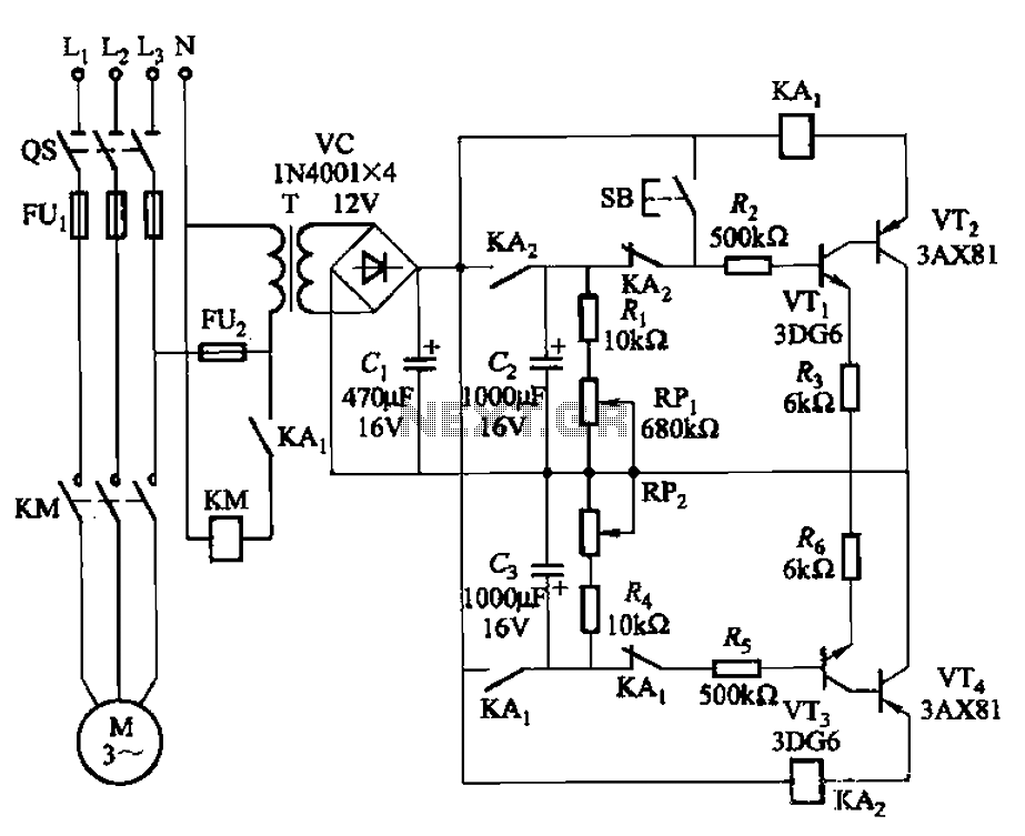
Intermittent start and stop cycle control circuit of the four
The circuit illustrated in Figure 3-79 consists of two delay circuits. The RPi adjustment potentiometer and RP2 can be modified to control the duration of the motor operation, allowing for arbitrary adjustments within a specified time frame.
The circuit comprises two...
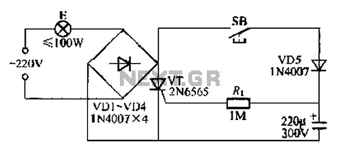
Simple light delay circuit 3
This circuit is a simple connection delay lamp circuit. When the lights are turned on and the switch is pressed, the power supply is activated. The capacitor charges rapidly, causing the thyristor (VT) to open, which in turn lights up...
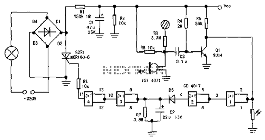
Practical three control delay self-extinguishing switch circuit schematics
The circuit diagram illustrates a sound, light, and touch-controlled delay self-extinguishing switch. It comprises three main sections: the power circuit, the signal conversion detecting circuit, a delay circuit, and a control circuit.
1. Power Circuit: This section consists of diodes...
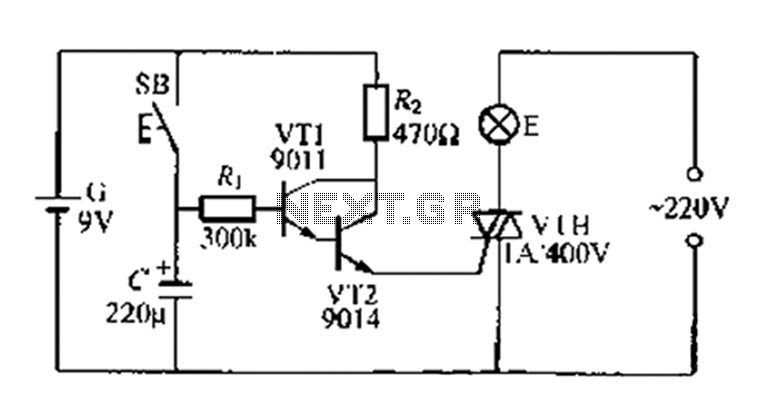
A delay circuit battery
A delay circuit utilizing an electric lamp. Normally, the thyristor VTH remains off, and the lamp E does not illuminate. The lamp turns on when needed, controlled by the FSH, with the VT1 and VT2 components forming a composite pipe...